Ot port, Table 7, Describes how the optimum – H3C Technologies H3C S12500 Series Switches User Manual
Page 70
57
Table 7 Selection of the optimum configuration BPDU
Step
Actions
1
Upon receiving a configuration BPDU on a port, the device compares the priority of the
received configuration BPDU with that of the configuration BPDU generated by the port, and:
•
If the former priority is lower, the device discards the received configuration BPDU and
keeps the configuration BPDU the port generated.
•
If the former priority is higher, the device replaces the content of the configuration BPDU
generated by the port with the content of the received configuration BPDU.
2
The device compares the configuration BPDUs of all the ports and chooses the optimum
configuration BPDU.
The following are the principles of configuration BPDU comparison:
{
The configuration BPDU with the lowest root bridge ID has the highest priority.
{
If configuration BPDUs have the same root bridge ID, their root path costs are compared. For
example, the root path cost in a configuration BPDU plus the path cost of a receiving port is S.
The configuration BPDU with the smallest S value has the highest priority.
{
If all configuration BPDUs have the same ports value, their designated bridge IDs, designated
port IDs, and the IDs of the receiving ports are compared in sequence. The configuration BPDU
containing a smaller ID is selected.
A tree-shape topology forms when the root bridge, root ports, and designated ports are selected.
The following describes with an example how the STP algorithm works. This example shows a simplified
spanning tree calculation process.
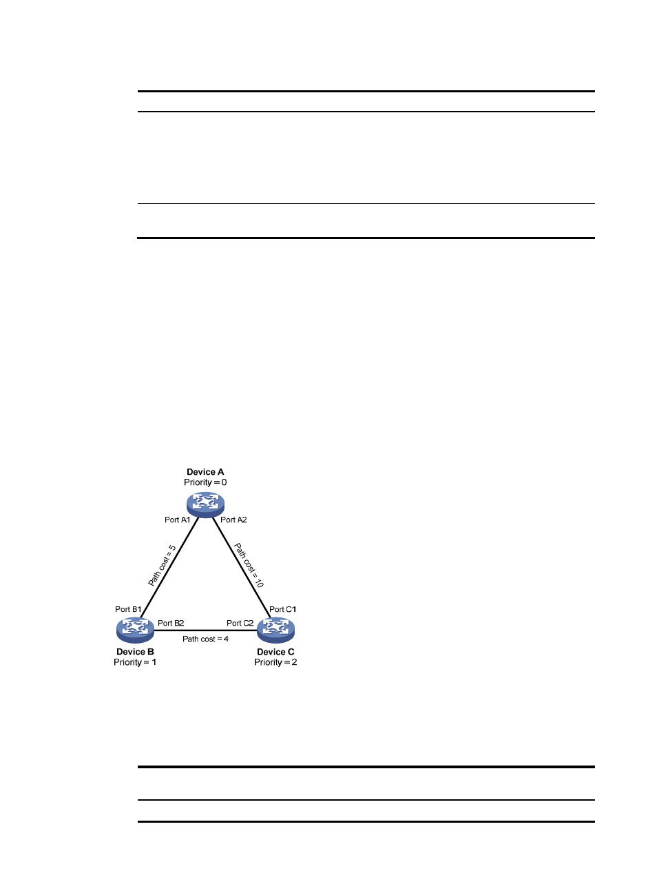
Figure 17 The STP algorithm
As shown in
, the priority values of Device A, Device B, and Device C are 0, 1, and 2, and the
path costs of links among the three devices are 5, 10, and 4.
4.
Initial state of each device
Table 8 Initial state of each device
Device
Port name
Configuration BPDU on the
port
Device A
Port A1
{0, 0, 0, Port A1}