Configuring switch a – H3C Technologies H3C S12500 Series Switches User Manual
Page 174
161
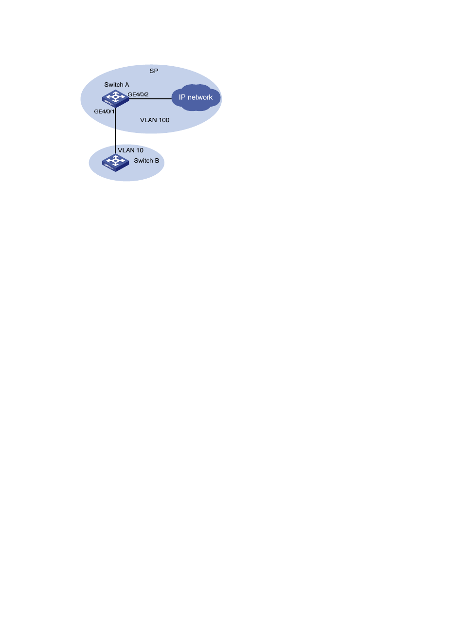
Figure 54 Network diagram
Configuring Switch A
# Create the CVLANs and SVLANs.
[SwitchA] vlan 10 to 100
# Configure uplink policy p1 to map CVLAN 10 to SVLAN 100.
[SwitchA] traffic classifier c1
[SwitchA-classifier-c1] if-match service-vlan-id 10
[SwitchA-classifier-c1] quit
[SwitchA] traffic behavior b1
[SwitchA-behavior-b1] remark service-vlan-id 100
[SwitchA-behavior-b1] quit
[SwitchA] qos policy p1
[SwitchA-policy-p1] classifier c1 behavior b1
[SwitchA-policy-p1] quit
# Configure downlink policy p11 to map the SVLAN back to the CVLAN.
[SwitchA] traffic classifier c11
[SwitchA-classifier-c11] if-match service-vlan-id 100
[SwitchA-classifier-c11] quit
[SwitchA] traffic behavior b11
[SwitchA-behavior-b11] remark service-vlan-id 10
[SwitchA-behavior-b11] quit
[SwitchA] qos policy p11
[SwitchA-policy-p11] classifier c11 behavior b11
[SwitchA-policy-p11] quit
# Assign customer-side port GigabitEthernet 4/0/1 to CVLAN 10 and SVLAN 100.
[SwitchA] interface gigabitethernet 4/0/1
[SwitchA-GigabitEthernet4/0/1] port link-type trunk
[SwitchA-GigabitEthernet4/0/1] port trunk permit vlan 10 100
# Apply uplink policy p1 to the incoming traffic and downlink policy p11 to the outgoing traffic
[SwitchA-GigabitEthernet4/0/1] qos apply policy p1 inbound
[SwitchA-GigabitEthernet4/0/1] qos apply policy p11 outbound