Pvst configuration example, Network requirements – H3C Technologies H3C S12500 Series Switches User Manual
Page 114
101
3 GigabitEthernet3/0/2 ALTE DISCARDING NONE
4 GigabitEthernet3/0/3 ROOT FORWARDING NONE
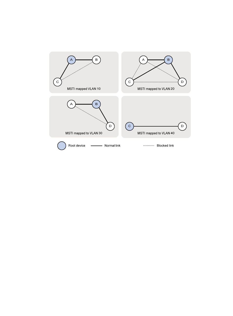
Based on the output, you can draw the MSTI mapped to each VLAN, as shown in
.
Figure 30 MSTIs mapped to different VLANs
PVST configuration example
Network requirements
As shown in
, Device A and Device B work at the distribution layer. Device C and Device D work
at the access layer.
Configure PVST so that packets of different VLANs are forwarded along different spanning trees.
VLAN 10, VLAN 20, and VLAN 30 are terminated on the distribution layer devices, and VLAN 40 is
terminated on the access layer devices. The root bridge of VLAN 10 and VLAN 20 is Device A, that of
VLAN 30 is Device B, and that of VLAN 40 is Device C.
This manual is related to the following products: