Configuration procedure – H3C Technologies H3C S12500 Series Switches User Manual
Page 217
204
•
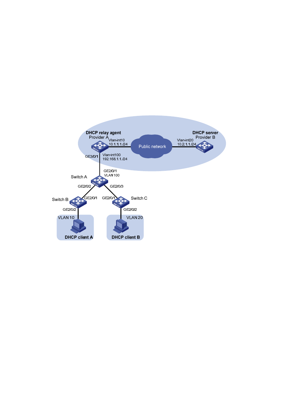
DHCP client A and DHCP client B are devices on the customer networks.
•
Provider A is the DHCP relay agent and Provider B is the DHCP server.
•
Provider A and Provider B communicate with each other through Layer 3 interfaces.
The expected results after the configuration are:
•
DHCP relay agent Provider A receives double-tagged packets sent from DHCP clients, terminates
these packets by removing their inner and outer VLAN tags, and forwards the packets to DHCP
server Provider B through the service provider network.
•
DHCP client A and client B can apply for IP addresses and related network configuration
parameters from Provider B through the service provider network.
Figure 75 Network diagram
Configuration procedure
1.
Configure DHCP relay agent Provider A:
# Enable DHCP service.
[ProviderA] dhcp enable
# Create the DHCP server group.
[ProviderA] dhcp relay server-group 1 ip 10.2.1.1
# Create VLAN-interface 100.
[ProviderA] vlan 100
[ProviderA-vlan100] quit
[ProviderA] interface vlan-interface 100
# Enable QinQ termination on the interface and specify VLANs 10 and 20 as the inner VLAN tags
that can be added to packets.
[ProviderA-Vlan-interface100] second-dot1q 10 20
# Enable the VLAN interface to transmit broadcast and multicast packets.
[ProviderA-Vlan-interface100] vlan-termination broadcast enable