Vlan mapping implementations, One-to-one vlan mapping – H3C Technologies H3C S12500 Series Switches User Manual
Page 164
151
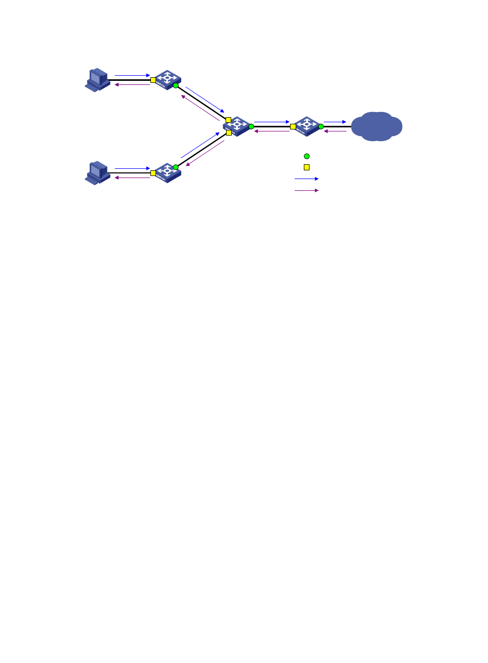
Figure 50 Basic VLAN mapping concepts
•
Uplink traffic—Traffic transmitted from the customer network to the service provider network.
•
Downlink traffic—Traffic transmitted from the service provider network to the customer network.
•
Network-side port—A port connected to or closer to the service provider network.
•
Customer-side port—A port connected to or closer to the customer network.
•
Uplink policy—A QoS policy that defines VLAN mapping rules for uplink traffic.
•
Downlink policy—A QoS policy that defines VLAN mapping rules for downlink traffic.
•
Customer VLANs (CVLANs)—VLANs assigned to customers.
•
Service provider VLANs (SVLANs)—VLANs assigned for transmitting traffic across the service
provider network.
For more information about QoS policies, see ACL and QoS Configuration Guide.
VLAN mapping implementations
This section describes how VLAN mapping is implemented on the switch.
One-to-one VLAN mapping
Implement one-to-one VLAN mapping through the following configurations, as shown in
•
Apply an uplink policy to the incoming traffic on the customer-side port, mapping each CVLAN ID
to a unique SVLAN ID. When a packet arrives, the switch replaces its CVLAN ID with the matching
SVLAN ID.
•
Apply a downlink policy to the outgoing traffic, mapping each SVLAN ID back to its corresponding
CVLAN ID. When forwarding a packet out of the port, the switch replaces its SVLAN ID with the
matching CVLAN ID.
SP
Network-side port
Customer-side port
Uplink traffic
Downlink traffic