Installation and cabling – Ensemble Designs 7555 HD / SD Video Processing Frame Synchronizer User Manual
Page 10
www.ensembledesigns.com
Avenue 7555, 9550, 9550-XA - Page 10
7555 HD/SD, 9550 3G/HD/SD, and 9550-XA 3G/HD/SD Video Processing Frame Synchronizers
Installation and Cabling
Configuring the Analog Audio and Balanced Digital Data Jumper
Connectors
Note:
This functionality requires the 9615 AES, analog audio, and data I/O software key
option.
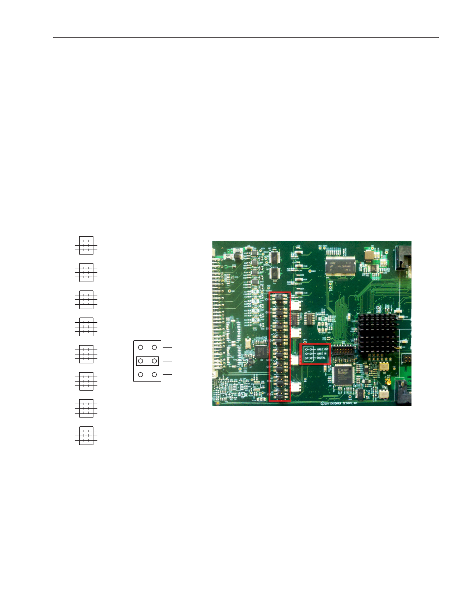
Before you can use the 15-pin D connector for analog audio out, analog audio in or digital, you must
first install analog audio and balanced digital data jumper connectors onto the module’s board.
There are eight connectors (four pairs) that map to the 15-pin D connector. Each connector has three
possible configurations—analog out, analog in, and digital data.
The 15-Pin D Connector and Digital Data (Dolby Metadata)
Unlike some other Avenue modules, the only purpose for the digital data capability of the 15-pin D
connector is for Dolby metadata; it cannot be used for serial control.
Note the portion of the board pictured above (outlined in
red) that resembles the illustration to the left.
The illustration to the left of the above photo reflects the placement of the connectors on the 7555,
9550 and 9550-XA boards (shown in the photograph on the right) for channels 1 through 4. The
positive and negative connectors for each channel are indicated on the board.
For each of the eight connectors, use the jumper to connect the top pair for analog audio out, the
middle pair for analog audio in, and the lower pair for digital data.
ANLG OUT
ANLG IN
DIGITAL
DATA
CH2+
CH2-
CH1-
CH1+
CH3+
CH3-
CH4+
CH4-