Ab c a b, Ac line configuration before, Ac line configuration after – Airaid 510-312 User Manual
Page 2
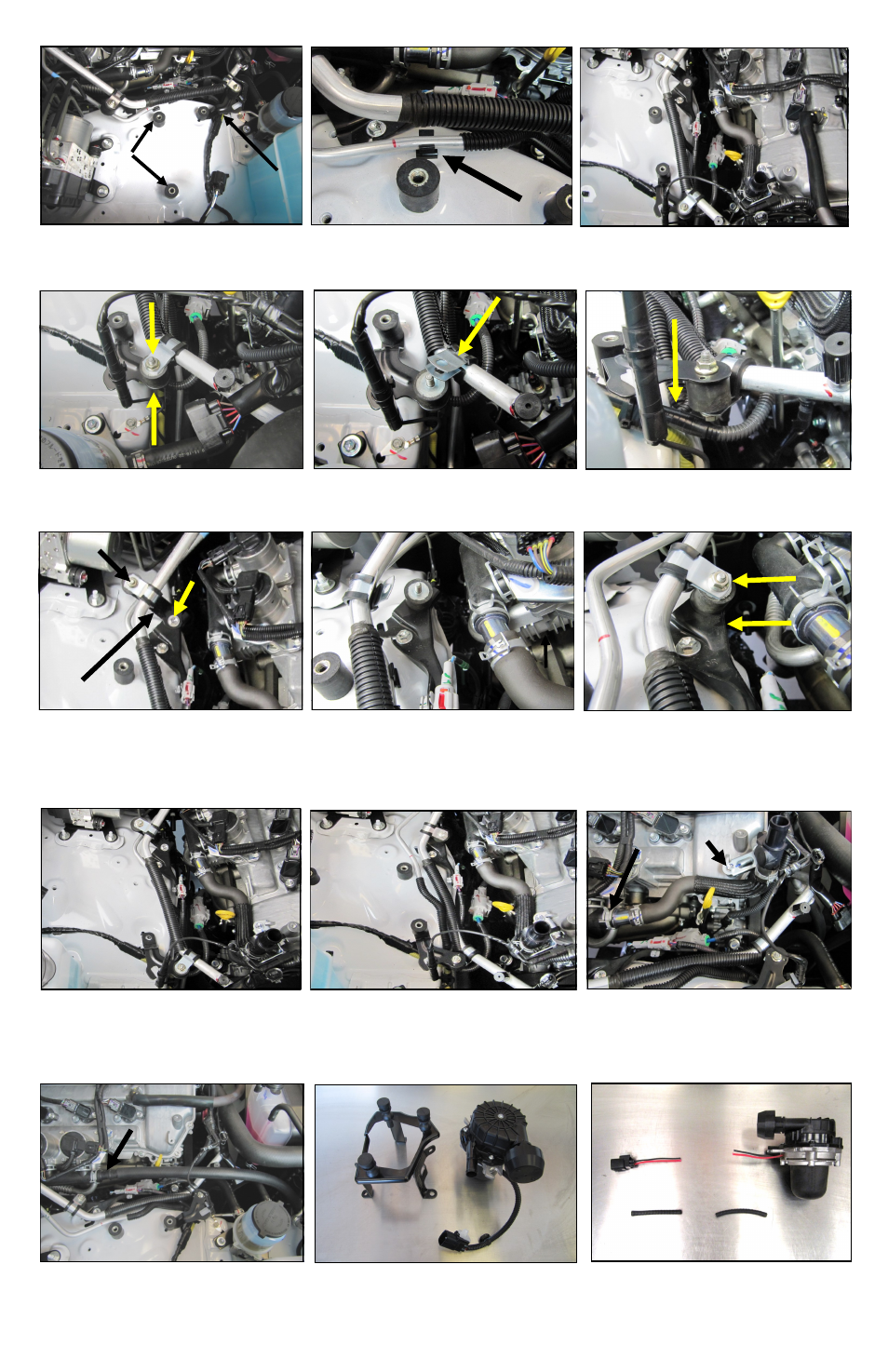
11. Separate the line from the vibration isolator and re-
move the clamp. Flip the clamp upside down from its
original position and reinstall the clamp back onto the
line.
14. Transfer the vibration isolator into the bolt hole from
step 13B. Separate the clamp from the AC line. Flip the
clamp upside down from its original position and rein-
stall the clamp back onto the line.
15. Remount the AC line to the vibration isolator using
the OEM 6mm nuts.
10.
Reconfigure the Forward AC line mount.
Remove the upper and lower 6mm nuts on the front AC
line mount.
16. Remove the air injection plumbing.
A. Compress the spring clamp on the manifold hose and
remove the hose and the metal insert.
B. Remove the 6mm bolt from the bracket on the valve
cover, disconnect the wiring harness, and remove the
air tubing, bracket and plastic fitting from the vehicle.
AC line configuration BEFORE
AC line configuration AFTER
13. Reconfigure the Rear AC line mount.
A. Remove the 6mm nuts and vibration isolator on the
rear AC line mount.
B. Remove the 6mm bolt from the line bracket.
C. Remove the line bracket from the vehicle. It will not
be reused
12. Remount the vibration isolator Under the factory
bracket and re secure the AC line using the OEM 6mm
nuts.
18. Separate the air pump from the rubber mounts on the
bracket and place it on a work bench.
17
.
Replace the OEM plumbing with the 3/4” hose (#9)
and the 3/4” Barbed fitting (#26). Route the hose to-
wards the radiator area of the vehicle for now.
19. Cut the air pump wire harness in half and remove the
factory loom. Early models will have two Primary wires,
Red and Black. Later models will have two Secondary
White wires in addition to the Primary wires.
A
B
C
A
B
FITTING
9. To create enough clearance in the inner fender area for
the intake system, the AC lines will need to be re posi-
tioned so that they will lay flat and side by side
.
7. Install two of the M8 CAB Mounts (#15), hand tight,
into the weld nuts on the inner fender as shown. Use the
third CAB Mount to replace the 8mm bolt holding the
A/C bracket.
8. Unclip the thin AC line from the fender clip and
remove the clip from the vehicle.
BRACKET