Airaid 200-104 User Manual
Installation instructions
Component Identification
1.
Airaid Premium Filter
1
2.
Plastic “Hat”
1
3.
13” x 3..5” Tube
1
4.
3.5” x 3.5” Coupler
1
5.
5.25” Gasket
1
6.
Black Speed Clamp
2
7.
Bent Black Stud
1
8.
Aluminum Polished Nut 1
9.
Silver Bracket
1
10.
90° Plastic Elbow
1
11.
½” x 4” Hose
1
12.
Rubber Grommet
1
13.
Serrated 5/16-18 Nut
1
14.
M6-1 Hex Nut
1
15.
5/16-18 x ¾ Hex Bolt
1
I
DISCONNECT NEGATIVE (-) BATTERY CABLE
II
Remove Factory Intake Assembly
A. Loosen the wing on the top of the factor y air intake assembly and r emove assembly from vehicle.
B. Remove and discard the 1” crankcase br eather r ing. See Fig#1 (save valve cover breather tube for later use)
C. Use a 13mm socket and wrench to r emove the str ap that secur es the silencer tube on the passenger side fender housing. See Fig#2
D. Remove entir e factory air cleaner assembly fr om vehicle.
III
1987-1992 : Install the AIRAID Throttle Body Stud and Airaid Hat
A. Replace the “S” shaped thr eaded stud into the top of the thr ottle body. (Note: also scr ew the 6mm ser rated nut onto the stud .) See Fig#3
IV
1993-1995: Install the AIRAID Throttle Body Stud and Airaid Hat
A. Remove the two air cleaner hold down studs with a 5/16” wr ench. See Fig# 4. Take car e not to loosen thr ottle body.
B. Scr ew the “S” shaped ¼”x20 thr eaded stud into the top of the thr ottle body. (Note: The factor y threaded hole is ¼”x20 thread, located in fr ont of the
injectors and between the throttle bores.) See Fig#3
C. Also scr ew the 6mm ser r ated nut onto the stud. See Fig#3
V
Mount the AIRAID Intake System Brace
A. Locate the dipstick tube mounting br acket on the passenger side cylinder head. Using a 3/8” socket, r emove the bolt and save for later use.
B. Carefully pull the dipstick away fr om the cylinder head and position the silver Air aid mounting br acket between the cylinder head and the dipstick
bracket. See Fig#5
C. Reinstall bolt and tighten loosely so that adjustments may be made later .
VI
Assemble and Install the AIRAID Intake System (Refer to Fig#6 & Fig#7)
A. Check for and r emove and foreign debris in the intake tube and filter .
B. Insert r ubber grommet into the hole in the r ear of the Air aid hat.
C. Insert the black plastic elbow into the gr ommet hole in the r ear of the Airaid hat.
D. Place the supplied gasket around the top per imeter of the thr ottle body.
E. Position the Air aid hat over the thr ottle body and guide over the Air aid stud.
F. Tighten the Air aid hat loosely with the billet nut pr ovided.
G. Insert ½”x 4” hose over plastic elbow and connect to valve cover br eather tube, secur e using the two black clamps pr ovided.
H. Slide the stainless steel clamp with r ubber insert over the opening of the Air aid hat.
I. Inser t the silver Air aid tube into the stainless steel coupler , connecting the tube to the hat.
J. Align the tab on the tube with the end of the br acket attached to the dipstick br acket and fasten with the har dwar e provided.
VI
Finishing Up
A. Tighten all clamps, brackets, nuts & bolts.
B. Inspect over all wor k and check hood clear ance.
C. Re-connect negative battery cable.
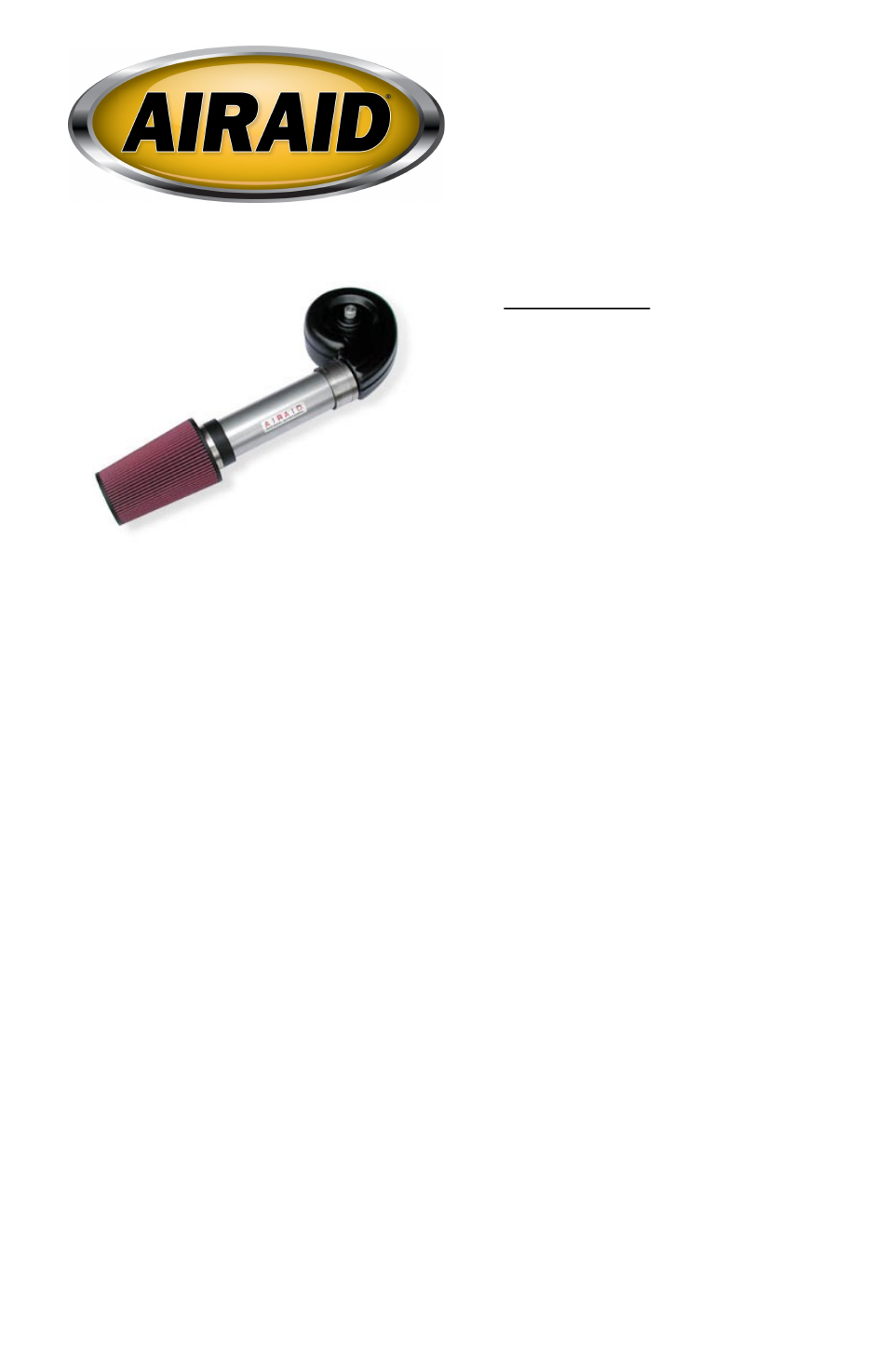
Installation Instructions
For Part Numbers:
200-104
700-420 Airaid Oiled Media Filter
201-104
701-420 SynthaMax Dry Media Filter - Red
202-104
702-420 SynthaMax Dry Media Filter - Black
203-104
703-420 SynthaMax Dry Media Filter - Blue
1988-95 Chevrolet Blazer/Tahoe
1988-95 Chevrolet C/K/R/V Pickup 10/ 20/ 30
1988-95 Chevrolet C/K/R/V Suburban 10/ 20
1988-95 GMC Jimmy/Yukon
1988-95 GMC C/K/R/V Pickup 1500/ 2500/ 3500
1988-95 GMC C/K/R/V Suburban 1500/ 2500
4.3L V6, 5.0L V8, 5.7L V8
Full color instructions can be viewed on our web site at Airaid.com. Use the Product Search function to find your part number, and click View Details.