Emerson SM-ETHERCAT 0471-0128-02 User Manual
Page 14
14
SM-EtherCAT User Guide
www.controltechniques.com
Issue Number: 2
5.1.3
Configuring the SM-EtherCAT module for cyclic communications
Unlike other Control Techniques fieldbus communication protocols, CoE does not
require that any module parameters be changed in order to achieve communications.
The baud rate of the network is fixed and the module is automatically allocated an
address.
To check that the ethernet cable connected to the SM-EtherCAT module on the drive is
connected correctly, look at the LED on the front of the SM-EtherCAT module relating to
the connector being used, if this light is a solid green color then a link is established with
the master, if this light if off then check the cabling and also check that the master has
started communications.
In the master, scan the network ensuring that the SM-EtherCAT module is connected
correctly to the master. If the network is configured correctly the SM-EtherCAT node(s)
should be visible in the PLC Master.
Decide on the input / output data you wish to send cyclically (objects and/or
parameters).
Cyclic data is implemented on CoE networks by using "Process Data Objects" or PDOs.
Separate data objects are used for receiving (TxPDOs - from the slave to the master)
and transmitting (RxPDOs - from the master to the slave) data.
These PDOs contain the cyclic data (objects and/or parameters), the RxPDOs available
are 1, 2, 6 and 22, the TxPDOs available are 1, 2, 3, 6 and 22 (for more information on
these PDOs including default mappings please see section 6.1.2 RxPDO mappings on
page 21 and section 6.1.3 TxPDO mappings on page 23).
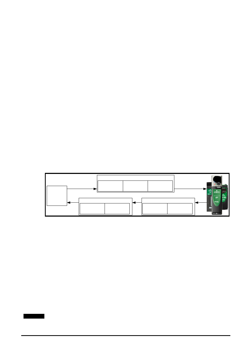
Figure 5-1 SM-EtherCAT PDO configuration
RxPDO1, TxPDO1 and TxPDO6 will need to be enabled in the master. Once enabled
you will need to add mappings to the PDOs.
The format used when mapping objects to PDOs is as follows:
•
Index: Object index number (0x0000)
•
Sub-index: Object sub-index number (0x00)
•
Size: Dependant on the size (in bytes) of the object to be mapped (range: 1-4)
The format of mapping drive parameters to PDO is as follows:
•
Index: 0x2000 + menu number
•
Sub-index: 0x00 + parameter number
•
Size: Dependant on the size (in bytes) of the object to be mapped (range: 1-4)
For example Pr 20.21 would be index 0x2014, sub-index 0x15 and the size would be 4
(the parameter is a 32-bit signed value).
The values are normally expressed in hexadecimal, so care must be taken to enter the
correct parameter number.
NOTE
0x6041
Status word
0x6064 position
actual value
TxPDO1
Pr 18.22
Pr 20.22
TxPDO6
PLC
0x6040
Control word
0x6042
vl_target_velocity
Pr 20.21
RxPDO1