Replaceable assemblies, Covers, Circuit board assembly – Visara 1174-65S User Manual
Page 36: Circuit board, removal, Cover, removal
30
1174-65S/90S Communications Servers Hardware Reference Manual
707020-002
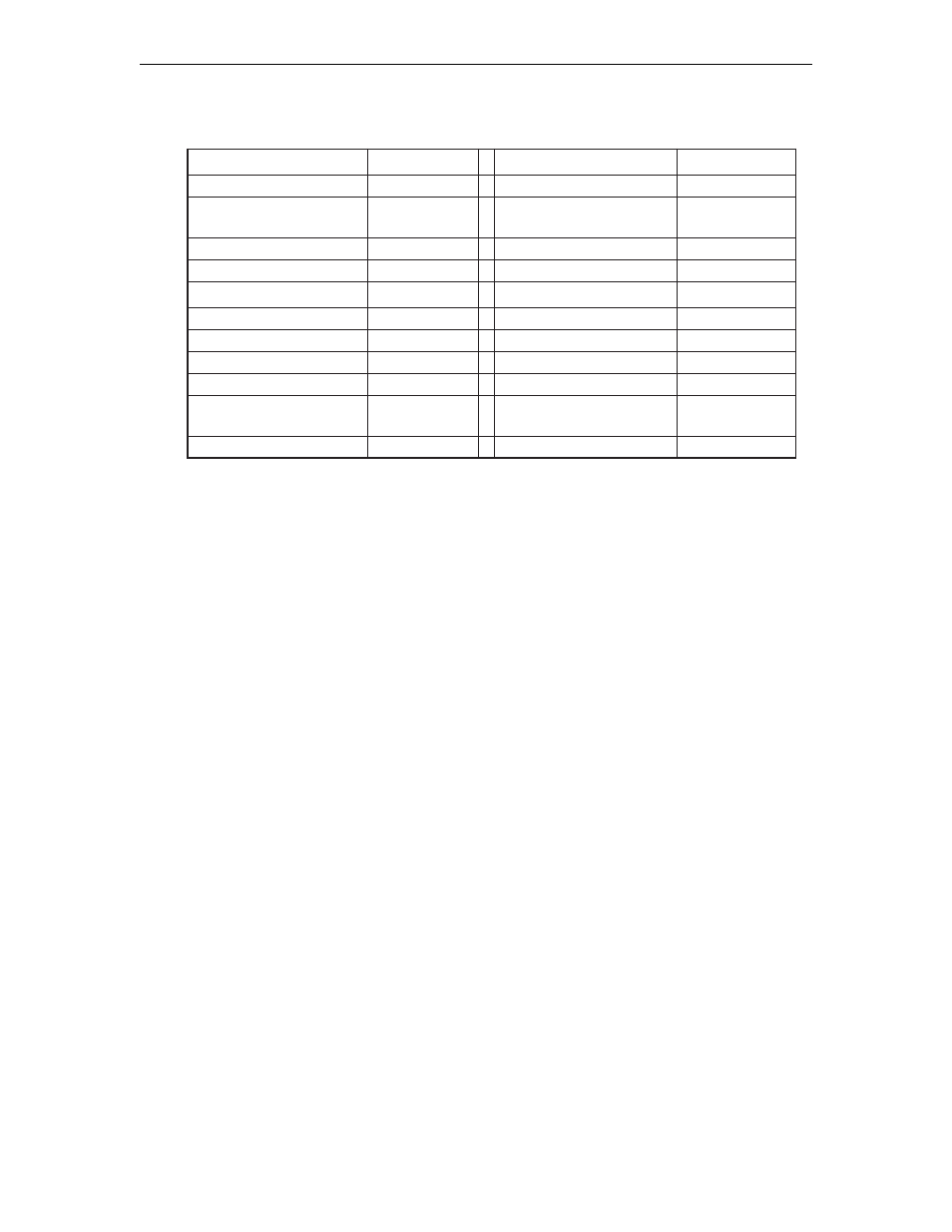
Replaceable Assemblies
n
o
i
t
p
i
r
c
s
e
D
N
/
P
a
r
a
s
i
V
n
o
i
t
p
i
r
c
s
e
D
N
/
P
a
r
a
s
i
V
)
y
l
n
o
S
5
6
(
A
D
A
1
4
9
/
0
0
9
-
1
6
5
0
1
2
)
y
l
n
o
S
5
6
(
C
S
H
6
0
9
-
5
6
2
0
2
2
)
y
l
n
o
S
5
6
(
C
I
A
1
4
0
/
1
0
0
-
0
6
5
0
1
2
e
l
b
a
C
r
e
t
p
a
d
A
C
S
H
)
y
l
n
o
S
5
6
(
1
0
0
-
0
1
2
0
2
2
)
y
l
n
o
S
5
6
(
t
r
o
P
-
8
1
,
A
D
C
2
5
9
/
2
1
9
-
7
5
5
0
1
2
d
r
a
o
B
r
e
h
t
o
M
0
4
2
/
0
0
2
-
4
2
2
0
2
2
t
r
o
P
-
9
,
A
D
C
1
5
9
/
1
1
9
-
7
5
5
0
1
2
l
e
n
a
P
r
o
t
a
r
e
p
O
1
0
0
-
0
0
7
1
1
2
H
T
E
6
4
9
/
6
0
9
-
0
3
4
3
1
2
)
y
l
n
o
S
5
6
(
1
M
I
L
P
1
0
0
-
7
0
7
8
6
9
T
E
F
6
0
9
-
3
7
2
0
2
2
)
y
l
n
o
S
5
6
(
2
M
I
L
P
1
0
0
-
8
0
7
8
6
9
e
l
b
a
C
k
s
i
D
y
p
p
o
l
F
3
0
0
-
7
6
4
6
0
2
y
l
p
p
u
S
r
e
w
o
P
1
0
0
-
2
5
6
0
1
2
e
v
i
r
D
k
s
i
D
y
p
p
o
l
F
2
0
0
-
0
4
1
5
0
2
)
5
3
.
V
/
2
3
2
-
S
R
(
C
C
S
6
0
9
-
5
5
5
0
1
2
)
y
l
n
o
S
5
6
(
e
v
i
r
D
k
s
i
D
d
r
a
H
4
0
0
-
4
7
6
0
1
2
)
C
n
e
G
(
s
/
b
M
4
/
6
1
,
I
I
C
R
T
6
0
9
-
7
1
6
6
0
2
l
a
n
g
i
S
,
e
l
b
a
C
D
D
H
)
y
l
n
o
S
5
6
(
2
0
0
-
1
2
4
6
0
2
P
H
V
6
0
9
-
1
7
2
0
2
2
P
P
H
6
0
9
-
4
1
6
6
0
2
Note: Part numbers listed following “/” indicate the assembly with packaging.
Covers
The back plate and main covers must be removed to gain internal access to the 1174-65S.
Removal
1. Ensure power is off.
2. Mark all cables properly for reinstallation before removing covers.
3. Remove all cables from the back of the unit.
4. Remove screws attaching the rear panel metal cover. Remove the rear panel cover.
5. Remove the four screws attaching the main cover to the unit chassis.
6. Slide the main cover toward the front of the unit to remove it from the chassis.
Replacement
1. Reverse the procedure to replace the covers.
2. Reattach all cables to the proper connectors.
Circuit Board Assembly
Each Circuit board assembly is held in place by captive fastening screws located at the
top of the rear guide bracket.
Removal
1. Ensure power is off. Remove the main cover.
2. Locate the Circuit board to be removed. For board slots J04-J09, loosen the fastening
screws holding the front board guide racket in place. Slide the bracket clear of the boards.
3. Loosen the captive screw attaching the board to the rear bracket (CDA boards have two
captive screws).
4. Lift the board from its Mother board connector and slide it clear of the unit.