Power cable requirements – Visara 1174-65S User Manual
Page 12
6
1174-65S/90S Communications Servers Hardware Reference Manual
707020-002
e
d
o
C
r
o
t
c
e
n
n
o
C
r
o
/
d
n
a
a
i
d
e
M
e
l
b
a
C
h
t
g
n
e
L
e
l
b
a
C
A
e
l
b
a
C
l
a
i
x
a
o
C
)
m
0
0
5
1
(
t
f
0
2
9
4
B
a
i
d
e
M
d
e
i
f
i
c
e
p
s
3
e
p
y
T
M
B
I
m
u
m
i
n
i
m
)
m
5
.
0
3
(
t
f
0
0
1
m
u
m
i
x
a
m
)
m
5
7
2
(
t
f
0
0
9
C
9
d
n
a
,
2
,
1
s
e
p
y
T
m
e
t
s
y
S
g
n
i
l
b
a
C
M
B
I
:
2
d
n
a
1
s
e
p
y
T
)
m
0
0
5
1
(
t
f
0
2
9
4
-
s
n
u
l
a
b
0
h
t
i
W
)
m
0
0
0
1
(
t
f
0
8
2
3
-
n
u
l
a
b
1
h
t
i
W
)
m
0
1
6
(
t
f
0
0
0
2
-
s
n
u
l
a
b
2
h
t
i
W
)
m
0
0
0
1
(
t
f
0
8
2
3
-
s
n
u
l
a
b
0
h
t
i
W
:
9
e
p
y
T
)
m
7
6
6
(
t
f
6
8
1
2
-
n
u
l
a
b
1
h
t
i
W
)
m
6
0
4
(
t
f
3
3
3
1
-
s
n
u
l
a
b
2
h
t
i
W
D
r
e
t
p
a
d
A
r
i
a
P
-
d
e
t
s
i
w
T
-
o
t
-
x
a
o
C
0
7
2
3
)
m
5
.
5
(
t
f
8
1
E
r
o
t
c
e
n
n
o
C
3
e
p
y
T
C
P
D
M
B
I
)
m
5
.
4
(
t
f
5
1
F
x
a
o
C
s
s
e
l
-
e
l
b
a
C
r
o
y
l
b
m
e
s
s
A
n
u
l
a
B
x
a
o
C
n
u
l
a
B
)
m
9
.
4
(
t
f
6
1
r
o
)
m
4
.
2
(
t
f
8
G
e
l
b
a
C
t
n
e
m
h
c
a
t
t
A
r
o
t
c
e
n
n
o
C
e
s
o
p
r
u
P
l
a
u
D
)
m
9
(
t
f
0
3
r
o
)
m
4
.
2
(
t
f
8
H
n
i
d
e
l
l
a
t
s
n
i
A
D
F
e
v
a
h
t
s
u
m
(
e
l
b
a
C
c
i
t
p
O
r
e
b
i
F
,
n
o
r
c
i
m
5
2
1
/
5
.
2
6
)
r
e
v
r
e
S
s
n
o
i
t
a
c
i
n
u
m
m
o
C
n
o
r
c
i
m
0
4
1
/
0
0
1
5
e
p
y
T
m
e
t
s
y
S
g
n
i
l
b
a
C
M
B
I
n
o
r
c
i
m
5
2
1
/
0
5
r
o
)
m
0
0
5
1
(
t
f
0
2
9
4
I
n
i
d
e
l
l
a
t
s
n
i
A
W
T
e
v
a
h
t
s
u
m
(
e
r
i
W
d
e
t
s
i
w
T
)
r
e
v
r
e
S
s
n
o
i
t
a
c
i
n
u
m
m
o
C
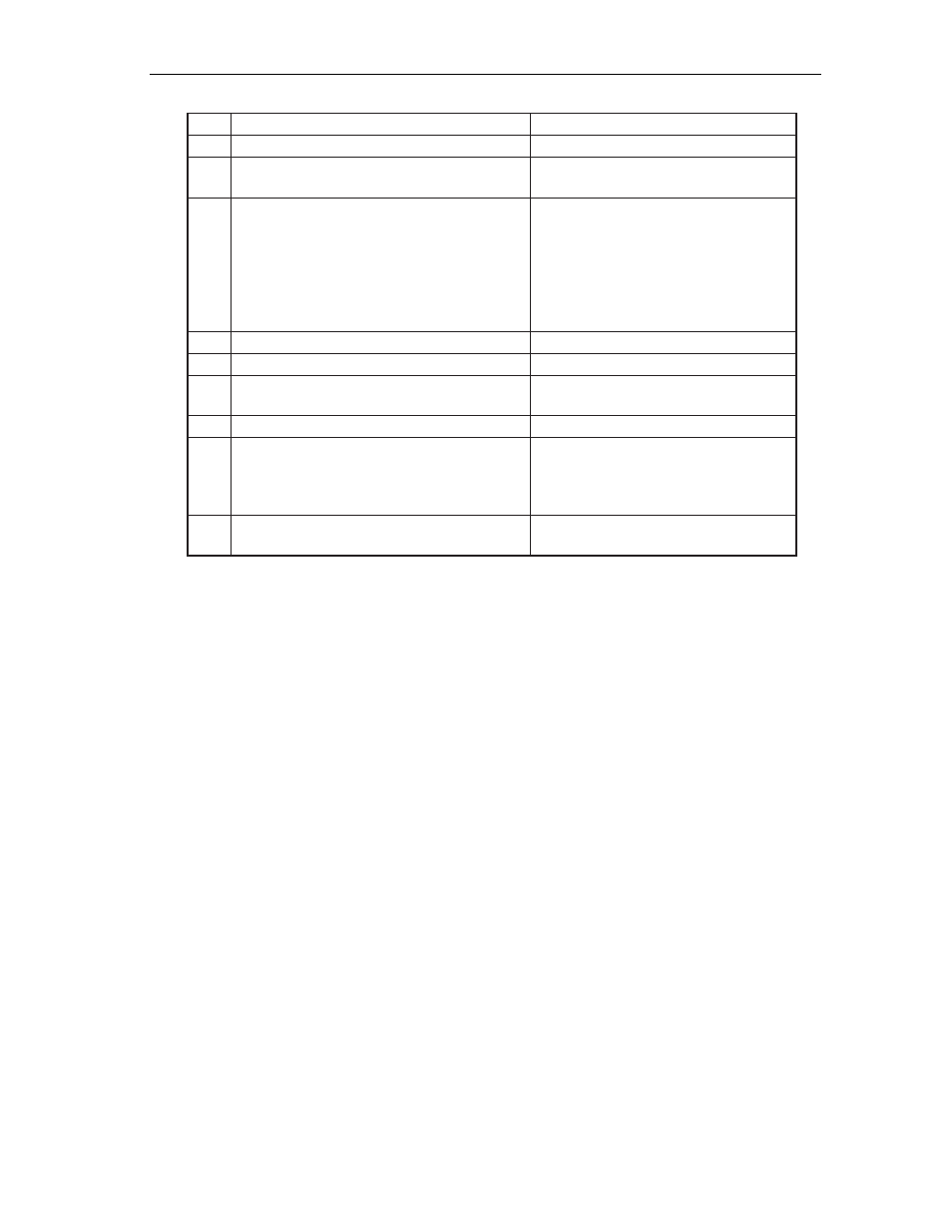
When using fiber optic cable, a Fiber Optic Device Adapter must be installed in the
Communications Server. Note that when using Type 3 media, a connector with a special
actuator and filter (such as IBM’s DPC-T3) is required in order to connect devices equipped
with a DPC. Otherwise, a Balun assembly is used.
The following limitations apply to the use of these devices:
1. (coax length) + (5 * twisted pair length) <= 4500 ft (1375 m)
2. (minimum twisted pair length) => 100 ft (30.5 m)
Power Cable Requirements
For units operating at 100-120V: The power cable required for domestic units is a UL listed,
CSA certified, 18/3 AWG, type SJT, cable (15-foot [4.57-meter] maximum). It is terminated
on one end by a 125V, 15A grounding type attachment plug. It is terminated at the other end
by a 125V, 15A parallel blade, grounding type attachment plug.
For units operating at 200-240V: The power cable required for domestic units is a UL listed,
CSA certified, 18/3 AWG, type SJT, cable (15-foot [4.57-meter] maximum). It is terminated
on one end by a 250V, 15A grounding type attachment plug. It is terminated at the other end
by a 250V, 15A tandem blade, grounding type attachment plug.
The power cable required for international units is an 18/3 AWG, type SJT, cable (15-foot
[4.57-meter] maximum). It is terminated on one end by a 250V, 15A grounding type attachment
plug body. It is terminated at the other end by a 250V, 15A grounding type cord connector.
The cord set is marked HAR to signify appropriate safety approvals. The socket outlet must
be nearby and easily accessible, per IEC 950 Sec. 1.7.2.