Verilink WANsuite 6x30 (34-00315.B) Product Manual User Manual
Page 48
3-20
W A N s u i t e 6 x 3 0
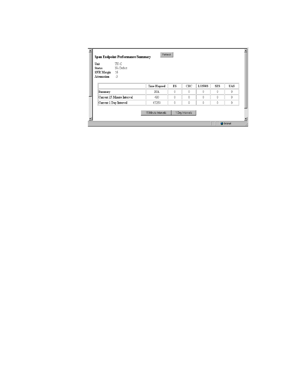
Clicking on the “Span Endpoint Performance/Summary” button on the Span
Endpoint Details screen will display the screen shown in Figure 3.17.
Figure 3.17
Span Endpoint Performance/Summary Screen
This screen displays information on the performance and error status of the
span endpoints. This information is provided in summary form for complete
totals as well as for current 15-minute and 1-day intervals.
S ta tu s
Current state of the endpoint. This is a bit-map of possible conditions. The
various bit positions are as follows:
1 (noDefect)
−
There no defects on the line.
2 (powerBackoff)
−
Indicates enhanced Power Backoff.
4 (deviceFault)
−
Indicates a vendor-dependent detection of diagnostics or
self-test results.
8 (dcContinuityFault)
−
Indicates vendor-dependent conditions that
interfere with span powering such as short and open circuits.
16 (snrMarginAlarm)
−
Indicates that the SNR margin has dropped below
the alarm threshold.
32 (loopAttenuationAlarm)
−
Indicates that the loop attenuation has
dropped below the alarm threshold.
64 (loswFailureAlarm)
−
Indicates a forward LOSW alarm.
128 (configInitFailure)
−
Endpoint failure during initialization due to paired
endpoint not able to support requested configuration.
256 (protocolInitFailure)
−
Endpoint failure during initialization due to
incompatible protocol used by the paired endpoint.
512 (noNeighborPresent)
−
Endpoint failure during initialization due to no
activation sequence detected from paired endpoint.
1024 (loopbackActive)
−
A loopback is currently active at this Segment
Endpoint.
S N R M argin
Current Signal-to-Noise Ratio margin for this endpoint as reported in a Status
Response/SNR message.