Port configuration, Port configuration -3 – Verilink HDM 2182 (880-502925-001) Product Manual User Manual
Page 19
HDM 2182 Quick Set-Up
Verilink HDM 2182 User Manual
2-3
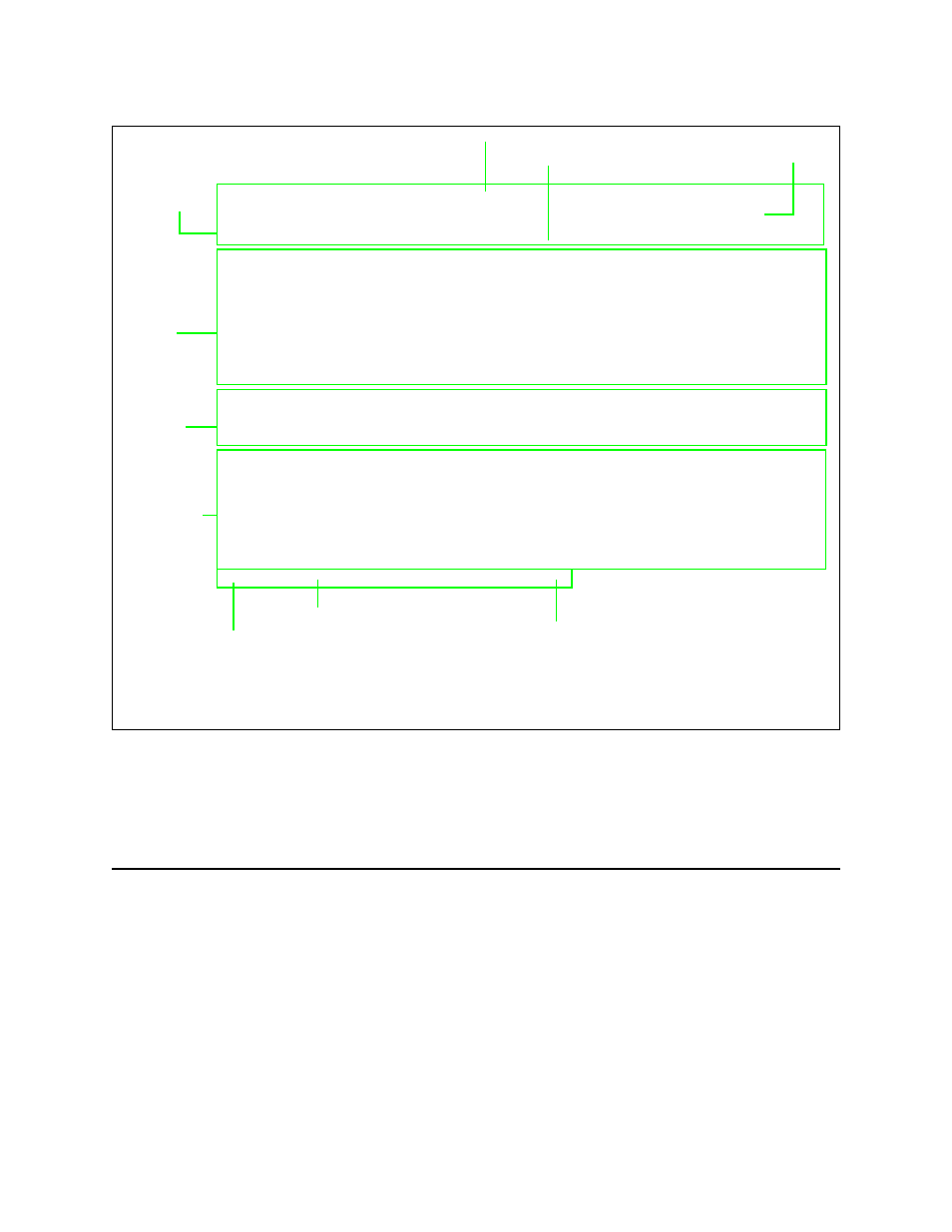
Figure 2-2 NCM Main Menu
From the NCM Craft interface Main Menu (
), select the
HDM application module using option S, Shelf/Slot. The Main Menu
uses brackets to enclose the G, indicating the HDM 2182 is now the
active module.
Port Configuration
From the Main Menu, select option C, “Configuration”, to start the
configuration task. The Configuration Menu displays (
The Configuration Menu is used to enable—or put in service—each
of the ports and to configure the various port parameters.
-- VERILINK NCM CONTROLLER : FW Rev 4.17, Dec 30 1997 12:33:20 --
-- VERILINK NCM CONTROLLER : FW Rev 4.17, Dec 30 1997 12:33:20 --
-- VERILINK NCM CONTROLLER : FW Rev 4.17, Dec 30 1997 12:33:20 --
-- VERILINK NCM CONTROLLER : FW Rev 4.17, Dec 30 1997 12:33:20 --
Site Name: Access Level: 2
Site Name: Access Level: 2
Site Name: Access Level: 2
Site Name: Access Level: 2
Managing at NEAR end node [127.255.255.0] Node ID: 0
Managing at NEAR end node [127.255.255.0] Node ID: 0
Managing at NEAR end node [127.255.255.0] Node ID: 0
Managing at NEAR end node [127.255.255.0] Node ID: 0
<- SLOT ->
<- SLOT ->
<- SLOT ->
<- SLOT ->
SHELF 1 2 3 4 5 6 7 8 9 10 11 12 13
SHELF 1 2 3 4 5 6 7 8 9 10 11 12 13
SHELF 1 2 3 4 5 6 7 8 9 10 11 12 13
SHELF 1 2 3 4 5 6 7 8 9 10 11 12 13
0 - - - - - - - - - - - - -
0 - - - - - - - - - - - - -
0 - - - - - - - - - - - - -
0 - - - - - - - - - - - - -
1 D [G] *N
1 D [G] *N
1 D [G] *N
1 D [G] *N
2 - - - - - - - - - - - - -
2 - - - - - - - - - - - - -
2 - - - - - - - - - - - - -
2 - - - - - - - - - - - - -
3 - - - - - - - - - - - - -
3 - - - - - - - - - - - - -
3 - - - - - - - - - - - - -
3 - - - - - - - - - - - - -
4 - - - - - - - - - - - - -
4 - - - - - - - - - - - - -
4 - - - - - - - - - - - - -
4 - - - - - - - - - - - - -
KEY:A=DIDCSU, B=DIU/DBU, C=CSU, D=DIU, E=SDIU, F=DIU/DDS, G=DHDM,
KEY:A=DIDCSU, B=DIU/DBU, C=CSU, D=DIU, E=SDIU, F=DIU/DDS, G=DHDM,
KEY:A=DIDCSU, B=DIU/DBU, C=CSU, D=DIU, E=SDIU, F=DIU/DDS, G=DHDM,
KEY:A=DIDCSU, B=DIU/DBU, C=CSU, D=DIU, E=SDIU, F=DIU/DDS, G=DHDM,
H=ATM/IMUX, I=IDCSU, J=PEP, M=IMUX, N=NCM, P=DPRI, Q=QUAD,
H=ATM/IMUX, I=IDCSU, J=PEP, M=IMUX, N=NCM, P=DPRI, Q=QUAD,
H=ATM/IMUX, I=IDCSU, J=PEP, M=IMUX, N=NCM, P=DPRI, Q=QUAD,
H=ATM/IMUX, I=IDCSU, J=PEP, M=IMUX, N=NCM, P=DPRI, Q=QUAD,
R=SUBRATE, T=HDM, U=DCSU, V=VCU, X=QPRI
R=SUBRATE, T=HDM, U=DCSU, V=VCU, X=QPRI
R=SUBRATE, T=HDM, U=DCSU, V=VCU, X=QPRI
R=SUBRATE, T=HDM, U=DCSU, V=VCU, X=QPRI
S) shelf/slot
S) shelf/slot
S) shelf/slot
S) shelf/slot
O) administration
O) administration
O) administration
O) administration
C) configuration
C) configuration
C) configuration
C) configuration
D) diagnostics
D) diagnostics
D) diagnostics
D) diagnostics
P) performance/status
P) performance/status
P) performance/status
P) performance/status
F) display far end DS3 port identification
F) display far end DS3 port identification
F) display far end DS3 port identification
F) display far end DS3 port identification
B) circuit manager
B) circuit manager
B) circuit manager
B) circuit manager
A) alarm
A) alarm
A) alarm
A) alarm
R) remote end setup
R) remote end setup
R) remote end setup
R) remote end setup
I) manufacturing info
I) manufacturing info
I) manufacturing info
I) manufacturing info
X) exit this screen
X) exit this screen
X) exit this screen
X) exit this screen
A [127.255.255.0] [1,1] HDM 2182 >
A [127.255.255.0] [1,1] HDM 2182 >
A [127.255.255.0] [1,1] HDM 2182 >
A [127.255.255.0] [1,1] HDM 2182 >
Menu Heading
Node “Map”
Location of
Command List
Firmware Version and Date of Release
Access Level (1-4)
Node Address
Data (Command) Entry Area
Module Key
❷ ❸
❶
❷
❸
❶
Brackets around module letter ( [G] ) indicate current module selected
Indicator for the type of shelf: M = Multi-line, Q = Quint-line, D = Dual-line
Asterisk indicates that the NCM is the Main Controller in the shelf
Area
(Physical
Modules)
Node Address
Active NCM Master Designator