Sundance SMT384 User Manual
Page 20
Version 1.4
Page 20 of 47
SMT384 User Manual
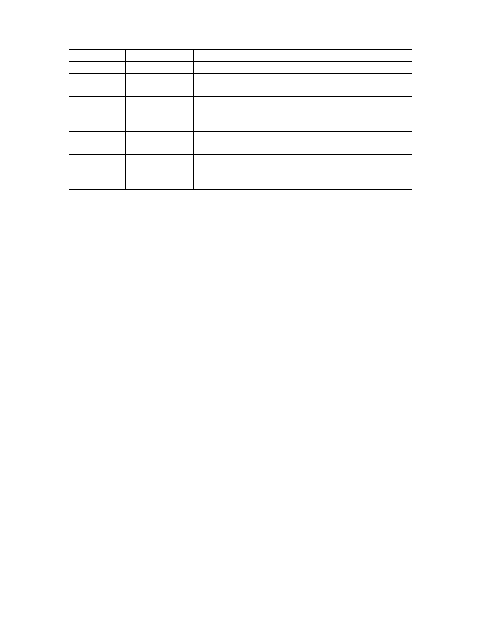
22 DGND Digital
Ground
23
D-12V0
Digital –12.0 Volts –used on the SM384 only for DC option.
24 DGND Digital
Ground
25 DGND Digital
Ground
26
EMU0
Emulation Control 0 – not used on SMT384
27
EMU1
Emulation Control 1 – not used on SMT384
28
TMS
JTAG Mode Control – not used on SMT384
29
nTRST
JTAG Reset – not used on SMT384
30
TCK
JTAG Test Clock – not used on SMT384
31
TDI
JTAG Test Input – not used on SMT384
32
TDO
JTAG Test Output – not used on SMT384
33 DGND Digital
Ground
Figure 10 – Mezzanine Module Interface Power Connector and Pinout.
The following few pages describes the signals on the data connector between the
main module and the daughter card. Bank A on the connector is used for the ADC
Channels A and B. Bank C is used for the ADC channels C and D. Bank B is used for
system clock and trigger signals, ADCs/Clock control signal.
- SMT107 (16 pages)
- SMT6035 v.2.2 (39 pages)
- SMT6012 v.4.6 (22 pages)
- FC100 (12 pages)
- FC108 v.1.1 (10 pages)
- SMT6065 v.4.0 (45 pages)
- FFT v.2.1 (19 pages)
- SMT111 (18 pages)
- SMT118LT (10 pages)
- SMT118 (20 pages)
- SMT123-SHB (13 pages)
- SMT128 (15 pages)
- SMT145 (18 pages)
- SMT148 (35 pages)
- SMT130 v.1.0 (46 pages)
- SMT148FX (48 pages)
- SMT310Q (55 pages)
- PARS (70 pages)
- SMT166-FMC (52 pages)
- SMT166 (44 pages)
- SMT300Q v.1.6 (61 pages)
- SMT310 v.1.6 (50 pages)
- SMT317 (24 pages)
- SMT326v2 (24 pages)
- SMT338 (19 pages)
- SMT349 (32 pages)
- SMT339 v.1.3 (27 pages)
- SMT338-VP (22 pages)
- SMT358 (25 pages)
- SMT351T (37 pages)
- SMT351 (25 pages)
- SMT350 (45 pages)
- SMT362 (30 pages)
- SMT365G (23 pages)
- SMT364 (37 pages)
- SMT373 (15 pages)
- SMT368 (24 pages)
- SMT370v3 (46 pages)
- SMT377 (22 pages)
- SMT381 2007 (31 pages)
- SMT381-VP (81 pages)
- SMT387 (42 pages)
- SMT391 (18 pages)
- SMT390-VP (55 pages)