Sundance SMT384 User Manual
Page 19
Version 1.4
Page 19 of 47
SMT384 User Manual
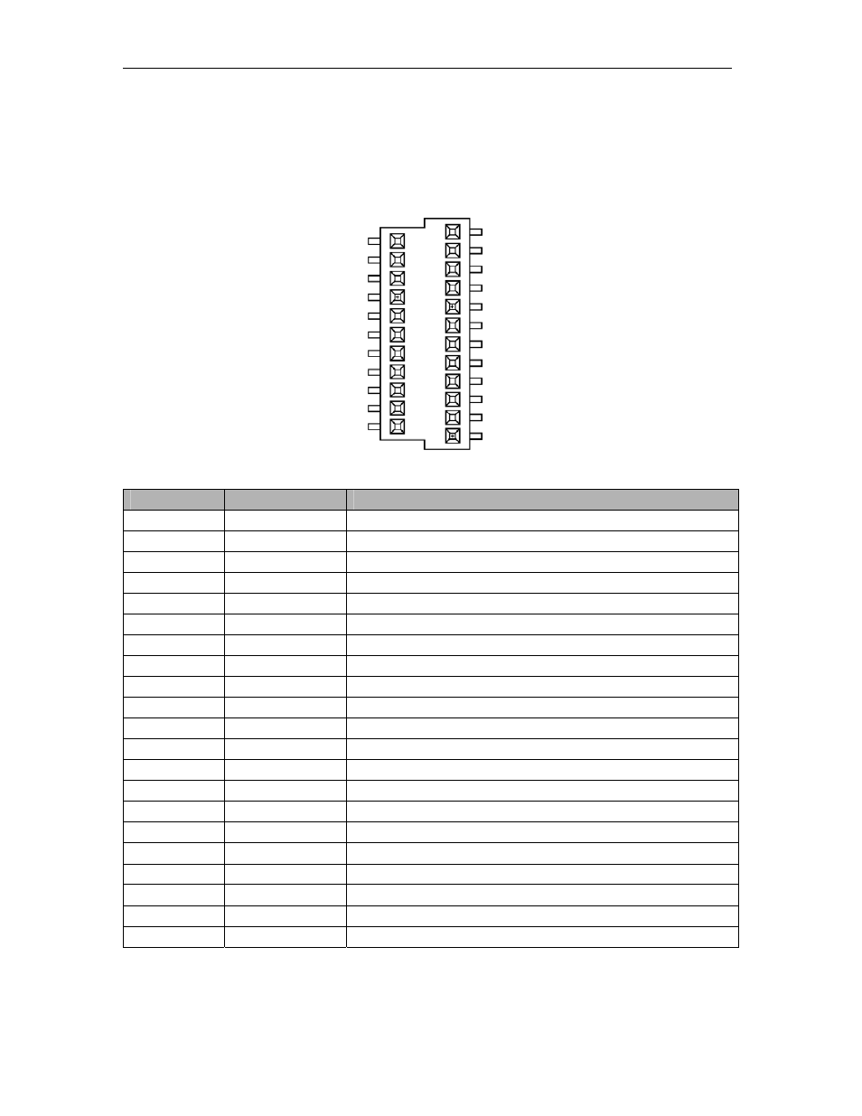
Some JTAG Lines are also mapped onto this connector to be used in case the
Daughter module would have a TI Processor. They would allow debugging and
programming via JTAG.
The following table shows the pin assignment on the power connector:
2
1
33
Pin Number
Pin Name
Description of Signal
1
D+3V3
Digital 3.3 Volts
2 DGND Digital
Ground
3
D+3V3
Digital 3.3 Volts
4 DGND Digital
Ground
5
D+3V3
Digital 3.3 Volts
6 DGND Digital
Ground
7
D+3V3
Digital 3.3 Volts
8 DGND Digital
Ground
9
D+5V0
Digital 5.0 Volts
10 DGND Digital
Ground
11
D+5V0
Digital 5.0 Volts
12 DGND Digital
Ground
13
D+5V0
Digital 5.0 Volts
14 DGND Digital
Ground
15
D+5V0
Digital 5.0 Volts
16 DGND Digital
Ground
17
D+12V0
Digital +12.0 Volts – not used on the SMT384
18 DGND Digital
Ground
19
D+12V0
Digital +12.0 Volts – not used on the SMT384
20 DGND Digital
Ground
21
D-12V0
Digital –12.0 Volts – used on the SMT384 only for DC option.