Sierra Video SVG Multi-Viewer User Manual
Page 32
SIERRA VIDEO
22
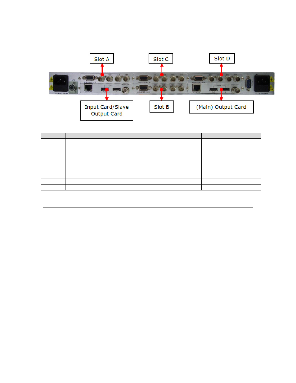
Description of rear panel.
The table of relationship between input source and inserted slots:
Slot
Module Type
Interface on Rear
Channel Name GUI
M
(Main)
Output card (Main)
HDMI IN
M1
S
(Slave)
Dual outputs system - Output card
(Slave)
HDMI IN
S1
Single output system - Input card
CH1, CH2, CH3, CH4
Group S: S1, S2, S3, S4
A
Input card inserted into Slot A
CH1, CH2, CH3, CH4
Group A: A1, A2, A3, A4
B
Input card inserted into Slot B
CH1, CH2, CH3, CH4
Group B: B1, B2, B3, B4
C
Input card inserted into Slot C
CH1, CH2, CH3, CH4 Group C: C1, C2, C3, C4
D
Input card inserted into Slot D
CH1, CH2, CH3, CH4 Group D: D1, D2, D3, D4
Note:
1. Inputs named CH1~CH4 on the rear panel of input card inserted into Slot A are
corresponding to A1~A4 on the browser GUI. The same for Group B, C and D.
2. If there is no input card inserted into a certain slot, like Slot A, the related channel group
(channel group A) will not be shown on the web page.
3. The input sources from each input module can only be displayed in its own four channels.
For example, input sources from Slot A can only be displayed in one channel or channels
from group A. Likewise for group B, C and D.
4.
For single output systems, an input card may be mounted in Slot S. For dual outputs,
Slot S is occupied by an output card.