Output module – Sierra Video Ponderosa 3G Series Routing Switcher User Manual
Page 50
SIERRA VIDEO
44
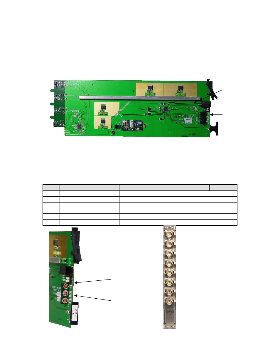
Output Module
Output modules are designed in groups of eight. This allows for expansion in groups of eight
outputs. Each output module comes with a rear “backplane” panel consisting of eight BNC
connectors.
The output module is installed from the front of the frame with the BNC panel installed directly
behind the output module in the back of the frame.
Output Module LEDs
Each output module has 5 Green LEDs located on the front edge of the board. The LEDs indicate
the status of the module’s voltage. All 5 LEDs must be lit for the module to operate properly. The
absence of any lighted LED indicates a failure of the module and the factory should be contacted.
Just behind the reset button there is a group of 6 LEDs used for de-bug purposes. The function of
the LEDs is described below.
LED
Indication
Normal condition
Color
1
Transmit in progress
Flickers On/OFF when data is transferred
GREEN
2
Application has run
ON
GREEN
3
Boot program has run
ON
GREEN
4
Temperature out of range
OFF
RED
5
Voltage out of range
OFF
RED
6
Not used
OFF
RED
Address Switches
BNC Rear Panel
De-bug LEDs
Voltage Status
LEDs
Reset Button
- Pro Series 64XL 1616 Series HD/SDI 3G Shasta HD Routing Switcher Shasta HD 88 HD Shasta HD 88 SDI 1601 Series HD/SDI Shasta HD Scanning Routing Switchers 1602 Series HD/SDI Shasta HD Routing Switchers 1602 Series HD/SDI Shasta HD Scanning Routing Switchers 1601 Series HD/SDI Dual Output Shasta HD Routing Switchers Pro XL Series 8 Pro XL Series 12 Alta Pro Series Tahoe 3232CAA Tahoe 32128V Lassen XL Series VS Lassen XL Series DE Lassen XL Series HD Lassen XL Series SDI Tahoe 3264VAA Tahoe Series 48 Tahoe Series 16 Tahoe Series 20 Shasta 88D Shasta 88E Shasta 1601D Shasta 1616D Tahoe Series 32 Shasta Series 16 Shasta Series 32 Pro XL Series 16 Pro XL Series 32 Viper Component Series Viper Composite Series