Crosspoint module – Sierra Video Ponderosa 3G Series Routing Switcher User Manual
Page 49
PONDEROSA
43
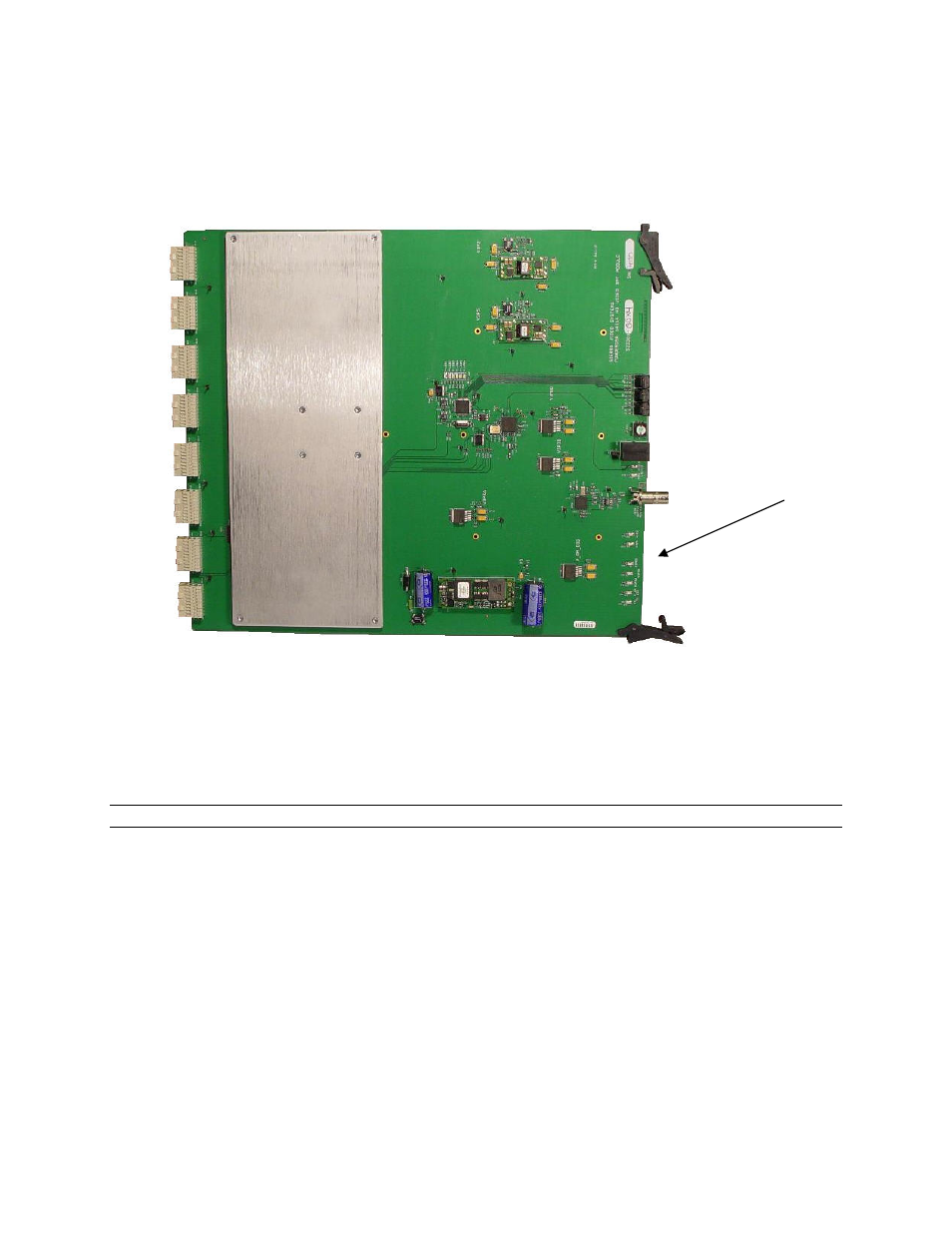
Crosspoint Module
The crosspoint module contains 1 crosspoint IC arranged to make a complete crosspoint array.
These ICs are located under the large metal heat sink in the middle of the board. Surrounding
the crosspoint array are IO buffers, the board control processor, and power supplies.
Crosspoint Module LEDs
There are 4 voltage status LEDs on the left side of the board. The LEDs indicate the status of the
module’s voltage. The LEDs on the right side of the board indicate CPU function and may vary
with code versions. All LEDs must be lit for the module to operate properly. The absence of any
lit voltage LED indicates a failure of the module and the factory should be contacted.
The factory should be contacted if any fault LEDs are lit.
Note:
The number of LEDs may vary in de-populated systems.
Voltage Status
LEDs
- Pro Series 64XL 1616 Series HD/SDI 3G Shasta HD Routing Switcher Shasta HD 88 HD Shasta HD 88 SDI 1601 Series HD/SDI Shasta HD Scanning Routing Switchers 1602 Series HD/SDI Shasta HD Routing Switchers 1602 Series HD/SDI Shasta HD Scanning Routing Switchers 1601 Series HD/SDI Dual Output Shasta HD Routing Switchers Pro XL Series 8 Pro XL Series 12 Alta Pro Series Tahoe 3232CAA Tahoe 32128V Lassen XL Series VS Lassen XL Series DE Lassen XL Series HD Lassen XL Series SDI Tahoe 3264VAA Tahoe Series 48 Tahoe Series 16 Tahoe Series 20 Shasta 88D Shasta 88E Shasta 1601D Shasta 1616D Tahoe Series 32 Shasta Series 16 Shasta Series 32 Pro XL Series 16 Pro XL Series 32 Viper Component Series Viper Composite Series