Genlock input – NewTek 3Play 330 User Manual
Page 28
Page 22
Hint: 3P
LAY
’s SDI and analog output sections can be used simultaneously. For example, for
an SD session you could choose Composite Output in the I/O Configuration panel (perhaps
to view 3P
LAY
output on a local composite monitor) at the same time as you use the SDI
connection to supply broadcast equipment. (See Section 6.7.1 for more on output
options.)
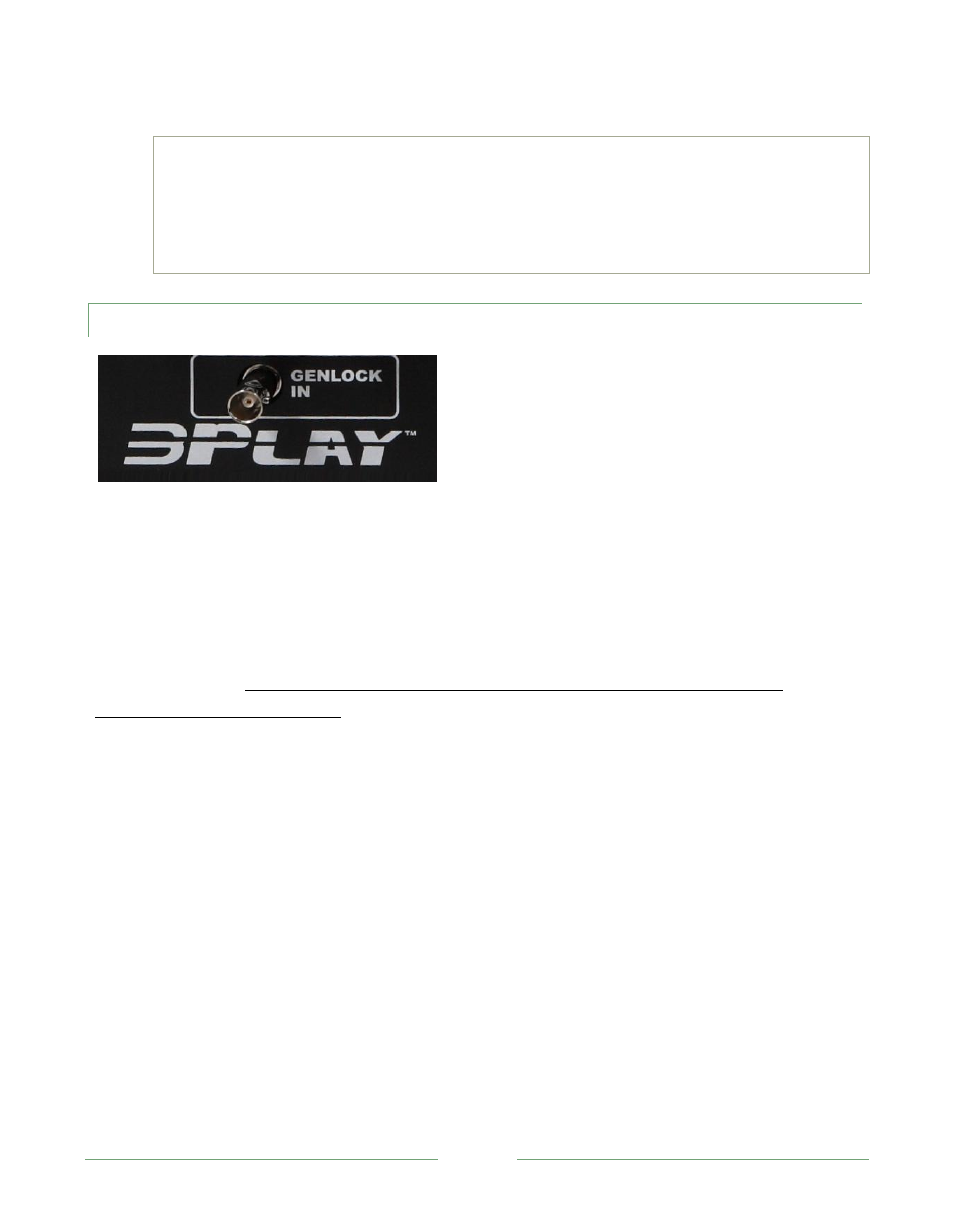
4.4.4 GENLOCK INPUT
Figure 8
The Genlock input on 3P
LAY
’s front panel is for connection of a ‘house sync’ or reference signal
(often a ‘black burst’). This is a common and important method of synchronizing equipment in the
video suite.
Genlocking is customary in higher end environments, and genlock inputs are usually found on
professional gear. If your equipment allows you to do so, you should genlock all cameras
supplying 3P
LAY
, and 3P
LAY
itself.
1. Supply the reference signal from the ‘house sync generator’ to 3P
LAY
’s Genlock connector.
2. If you haven’t already done so, genlock all cameras connected to 3P
LAY
inputs to the same
reference signal (see your camera manual for details).
3. Open a 3P
LAY
session from the Administration Screen, and access the I/O Configuration
panel (by clicking the small ‘gear’ icon at upper-right in the titlebar of the 3P
LAY
Desktop).
4. The default Reference Type in the Genlock settings is SD (Bi-level), as this is the most
common reference signal type. However, if you supply an HD reference signal to the
Genlock input, change the setting to HD (Tri-level).
5. Using downstream Waveform and Vector Scopes, adjust 3P
LAY
’s Horizontal and Vertical
Position and Phase settings (in the Genlock section of the I/O Configuration panel).