NewTek 3Play 330 User Manual
Page 26
Page 20
And of course, from 3P
LAY
’s outputs you may pass either of the above on to downstream live
switching and/or recording devices.
IMPORTANT NOTES:
THE DISPLAY CAPABILITIES OF ALL OUTPUT VIDEO DEVICES CONNECTED TO
3PLAY FOR A GIVEN SESSION MUST MATCH THE SESSION INPUT SETTINGS.
THE OUTPUT TYPE SETTING IN THE I/O CONFIGURATION PANEL MUST
CORRESPOND TO THE CONNECTED DEVICES (SEE SECTION 4.4.3).
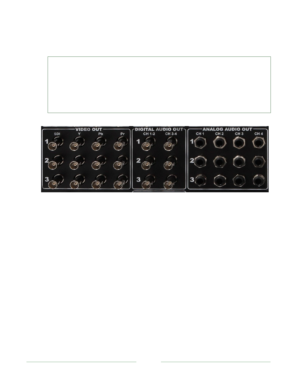
Figure 6
1. Connect downstream video devices to the output connectors, whether SDI, Component,
Y/C or Composite. Some devices may require use of RCA or 4-pin to BNC adapters.
Naturally, Composite and Y/C support SD resolution output only.
a. SDI
–
Attach the SDI connector to the BNC connector marked SDI.
b. Component – Attach the appropriate BNC connectors from your source to the
second, third and fourth BNC connectors (labeled Y, Pb and Pr).
c. Y/C
–
To connect Y/C devices, attach the Y (luma) connector of your source to the
third of four BNC connectors (labeled Pb). Attach the source’s C (chroma)
connector to the fourth connector (labeled Pr).
d. Composite - Attach the composite source’s connector to the second connector in
the Video Out section (labeled Y).