6 d/a converter reference jumper block, 7 range switch setting – Measurement Computing CIO-DAS16 User Manual
Page 7
1.6 D/A CONVERTER REFERENCE JUMPER BLOCK
There is a jumper block with 10 pins (2 rows of 5 each) located top center on the board. This block allows you to use the
on-board precision voltage reference or an external voltage to provide reference to either or both of the digital-to-analog
converters.
If you choose to use the on-board voltage reference rather than an external voltage, two D/A reference input pins, 10 and
26, on the 37-pin connector are not needed as reference inputs.
The 'S' jumper in this block is used to place a synchronizing signal on pin 26 so that the CIO-SSH16 external accessory
Simultaneous Sample & Hold board can be used.
If the on-board D/A reference is used, the jumpers are set in the I1 and I0
positions (Figure 1-6). The board is configured this way at the factory. The
SS&H output is not connected. If an external reference is desired, move the
blocks to X0 and X1. If using a CIO-SSH16 board, leave the blocks on I0
and I1 and place a block on SS&H. To avoid possible damage in the event
of a bad connection, do not install jumper S unless you intend to connect a
CIO-SSH16 board. There is a spare shorting block on one of the 'S' pins.
Figure 1-6. Ref. Volt and SS&H Jumpers
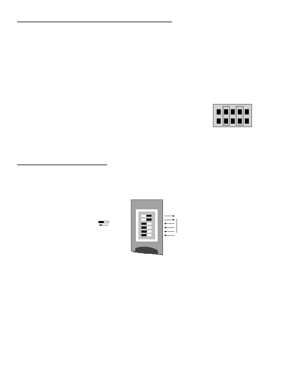
1.7 RANGE SWITCH SETTING
A bank of six dip switches accessible through the CIO-DAS16 connector bracket control the UNIPOLAR/BIPOLAR
analog input range (Figure 1-7).
Figure 1-7. Range Select Switches
These switches control the analog input range values of all channels. You can use Table 1-1 and Figure 1-7, or use the
InstaCal program to determine the correct positions of switches S1 through S6 for the range you desire.
.
3
D/A 0
INTERNAL &
EXTERNAL
D/A 1
EXTERNAL &
INTERNAL
X I1 S I0 X
BIPOLAR - SW 6 ONLY
USER GAIN SELECTED
SW 2 - 4
SELECT THE RANGE
6
5
4
3
2
1
S W #
U N I P O L A R
NO US E R GA I N
L E F T
The factory setting of +/- 5V shown.
SEE TABLE 1-1