1 common ground / single-ended inputs, 2 common ground / differential inputs, Single-ended – Measurement Computing CIO-DAS16 User Manual
Page 18: Input
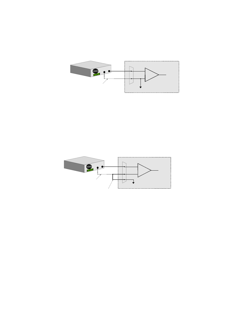
3.3.1 Common Ground / Single-Ended Inputs
Single-ended is the recommended configuration for common ground connections. However, if some of your inputs are
common ground and some are not, we recommend you use the differential mode. There is no performance penalty (other
than loss of channels) for using a differential input to measure a common ground signal source. However the reverse is
not true. Figure 3-4 below shows a recommended connection diagram for a common ground / single-ended input system
.
NOTE: For simplicity, the input multiplexer is not shown in the following diagrams.
O Figure 3-4.
Single-Ended
Input
3.3.2 Common Ground / Differential Inputs
The use of differential inputs to monitor a signal source with a common ground is a acceptable configuration though it
requires more wiring and offers fewer channels than selecting a single-ended configuration. Figure 3-5 shows the
recommended connections in this configuration.
Figure 3-5. Common Ground - Differential Input
14
+
-
In p u t
A m p
To A /D
A /D B o a rd
I/O
C o n n e c to r
LL G N D
C H IN
S ig
n a l
S
o u rc e
w ith
C
o m m
o n G
n d
O p tio nal w ire
since sig na l sou rce
and A /D bo ard sh are
com m o n g round
S ig n a l s o urc e an d A /D b o a rd
s h a rin g c om m o n gro u n d c o n n e c te d
to s in g le -en d ed inp u t.
+
-
In p u t
A m p
To A /D
A /D B o a rd
I/O
C o n n e c to r
LL G N D
C H H igh
C H Low
S ig
n a l
S
o urce
w ith
C o m
m o n
G n d
O ptio nal w ire
since signa l source
and A /D bo ard sha re
com m on g round
R equ ired connection
of L L G N D to C H Low
S ign a l s o u rc e an d A /D bo a rd
s ha ring c o m m o n g ro u nd c on n e c te d
to d iffe re n tia l in pu t.