5 d/a registers – Measurement Computing CIO-DAS16 User Manual
Page 25
READ:
The signals present at the inputs are read as one byte, the digital input data being contained in the four least significant
bits. The pins 25 (digital input 0) and 24 (digital input 2) digital inputs have two functions each.
The TRIG function of digital input 0 may be used to hold off the first sample of an A/D set by holding it low (0V) until
you are ready to take samples, which are then paced by the 82C54. It can also be used as the source of an external start
conversion pulse, synchronizing A/D conversions to some external event.
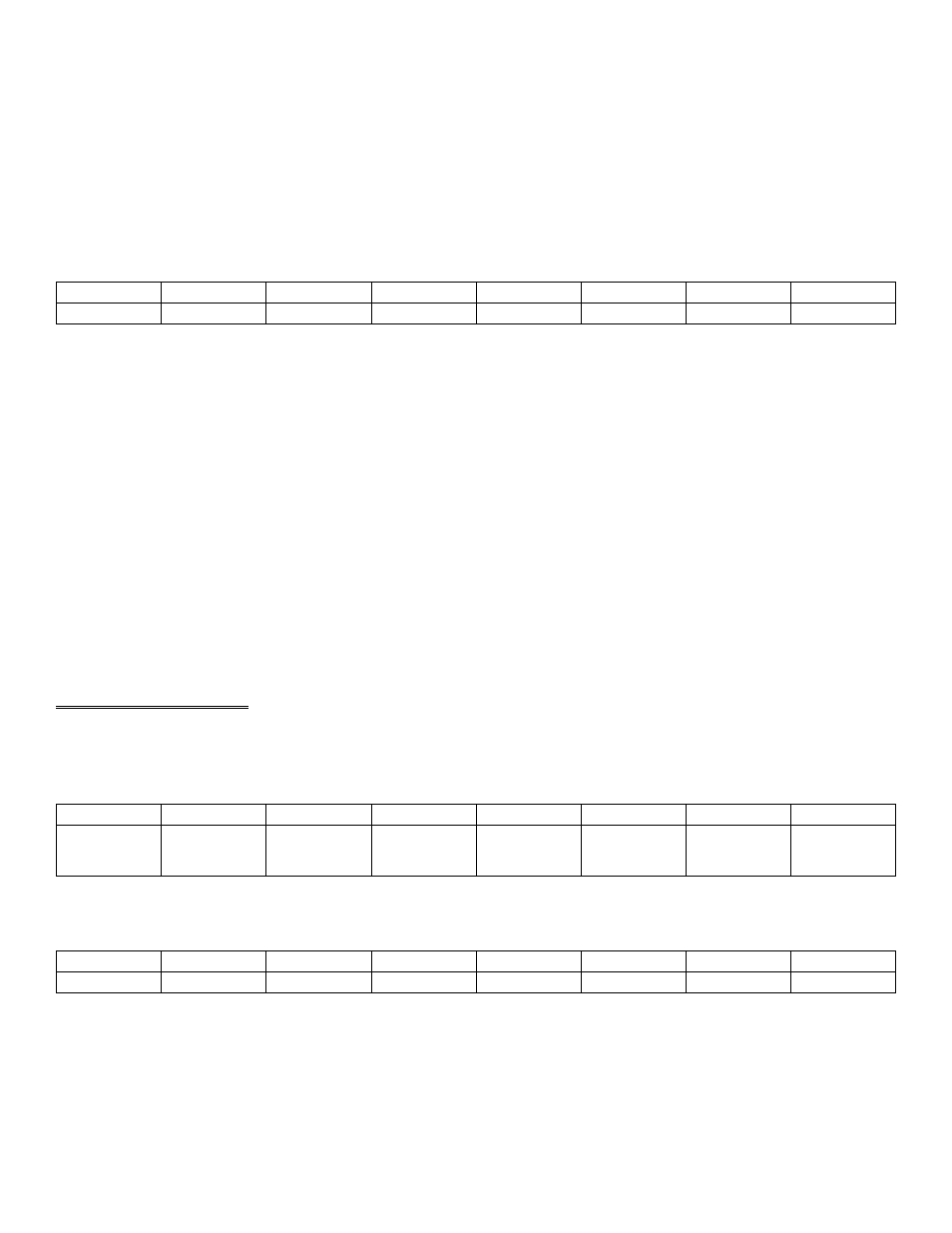
BASE ADDRESS +3
DO0
DO1
DO2
DO3
X
X
X
X
0
1
2
3
4
5
6
7
WRITE:
The upper four bits are ignored. The lower four bits are latched TTL outputs. Once written, the state of the inputs cannot
be read back because a read back would read the separate digital input lines (see above).
NOTE
The digital lines 0 to 4, pins 3, 4, 5, 6, 22, 23, 24, and 25 of the analog connector should not be used as
ON/OFF Digital I/O. Read on.
The digital inputs have multiple functions as described above. The digital outputs are also used by the CIO-EXP family
of multiplexer expansion boards. The original DAS-16 design had insufficient number of digital I/O, so we added a
PIO-12 compatible 24-line 8255 to the design. We suggest that you use these lines for ON/OFF digital functions, keeping
the 4-bit ports on the analog connector free.
4.5 D/A REGISTERS
D/A 0 REGISTERS
BASE ADDRESS +4
X
X
X
X
D/A12
LSB
D/A11
D/A10
D/A9
0
1
2
3
4
5
6
7
BASE ADDRESS+5
D/A8
D/A7
D/A6
D/A5
D/A4
D/A3
D/A2
D/A1
0
1
2
3
4
5
6
7
21