Measurement Computing CIO-DAS16 User Manual
Page 6
1.3 DMA LEVEL SELECT
What kind of computer are you installing the board in? If it is an old XT then there are only two DMA levels available
and level 3 is probably used by the hard disk controller in your XT computer. Set the
DMA level switch to the level 1 position (Figure 1-3).
If you have an AT or 386 type computer the hard disk controller is not at level 1 or 3
so either level may be used.
There are other boards that use DMA levels. Some network boards and some
IEEE-488 interface boards do also. If you have other boards in your computer with
DMA level switches on them, they must have a different level setting.
Figure 1-3. DMA Level Select Switch
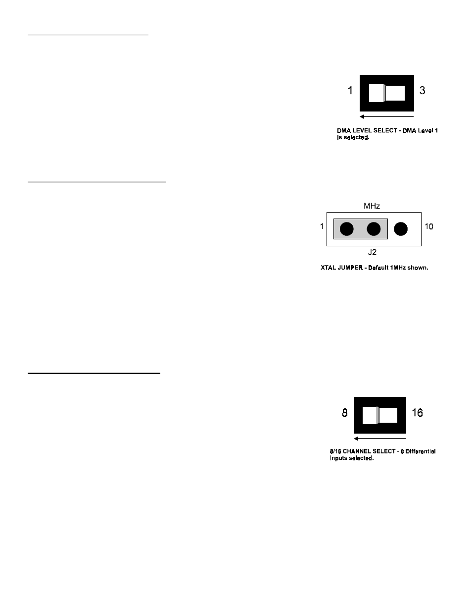
1.4 1/10 MHZ XTAL JUMPER
The 1/10 MHz XTAL jumper selects the frequency of the source applied to the
on-board pacer. This pacer is used to pace the A/D start conversion trigger.
This jumper is on the board because the original DAS-16, designed in 1984, had
a 1 MHz crystal. When MetraByte redesigned the DAS-16 and added the faster
10 MHz crystal, a jumper was provided to maintain compatibility with older
software. The CIO-DAS16 has the jumper because the DAS-16 has the jumper
and some software needs the jumper to be in the 1 MHz position and some
software requires the 10 MHz position.
Figure 1-4. 1 or 10 MHz Xtal Jumper
The CIO-DAS16 is shipped with the jumper in the 1 MHz position.
Some older 3rd party software programs require that the jumper be in the 1 MHz position. Please refer to the software
program user's manual for guidance. Other programs, such as Labtech Notebook, have a 1 or 10 MHz choice in the
set-up menu.
1.5 8/16 CHANNEL SELECT
The analog inputs of the CIO-DAS16 may be configured as 8 differential or 16
single-ended. Using single-ended inputs means you have more separate analog
input channels available to connect signals. Using differential inputs allows up to
10 volts of common mode (ground loop) rejection and can be more noise immune.
The CIO-DAS16 comes from the factory configured for 8 differential inputs so the
8/16 switch is in the position shown here. Set it for the type and number of inputs
you desire.
Figure 1-5. 8 /16 Channel Select Switch
2