6 status register – Measurement Computing CIO-DAS16 User Manual
Page 26
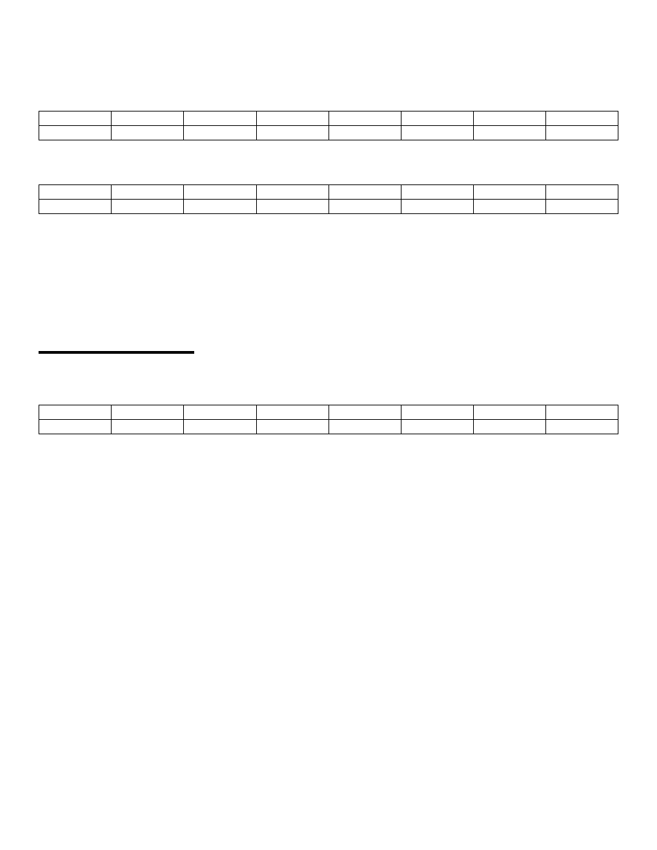
D/A 1 REGISTERS
BASE ADDRESS +6
X
X
X
X
D/A12
D/A11
D/A10
D/A9
0
1
2
3
4
5
6
7
BASE ADDRESS +7
D/A8
D/A7
D/A6
D/A5
D/A4
D/A3
D/A2
D/A1
0
1
2
3
4
5
6
7
WRITE ONLY:
Each 12-bit D/A output line has two registers. The first contains the four least significant bits of the data and four bits
that don't matter. The second register contains the eight most significant bits of the data.
The D/A will be updated when the eight most significant bits (upper register) are written. In this way, the lower four bits
can be written with no effect on the D/A output until the remainder of the data is written to the upper eight bits.
4.6 STATUS REGISTER
BASE ADDRESS + 8
CH1
CH2
CH4
CH8
INT
MUX
U/B
EOC
0
1
2
3
4
5
6
7
A read mostly, one-function-write register.
READ:
EOC = 1, the A/D converter is busy. EOC = 0, it is free.
U/B = 1, the amplifier is in Unipolar mode. U/B = 0, is bipolar.
MUX = 1, Channels are configured 16 single ended. MUX = 0, 8 differential.
INT = 1, an external pulse has been received. INT = 0, the flip-flop is ready to receive a pulse..
There is a flip-flop on the TRIGGER input (pin 25) which will latch a pulse as short as 200 ns. After being triggered, this
flip-flop must be reset by a write to this register. Your interrupt service routine must do this before another interrupt
trigger can be received.
CH8, CH4, CH2 and CH1 make up a binary number between 0 and 15 indicating the channel number that the MUX is
currently set to. It is valid only when EOC = 0. The channel MUX increments shortly after EOC = 1 so may be in a state
of transition when EOC = 1. The binary weight of each bit is shown in Table 4-1.
WRITE:
A write of any data to this register resets the flip-flop on the pin 25 input and sets the INT bit to 0.
22