3 channel mux scan limits register, 4 four-bit digital i/o registers – Measurement Computing CIO-DAS16 User Manual
Page 24
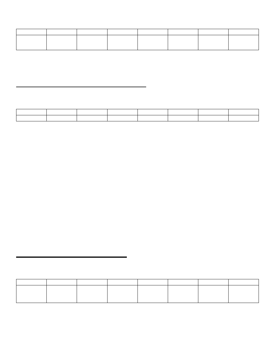
BASE ADDRESS +1
A/D8
A/D7
A/D6
A/D5
A/D4
A/D3
A/D 2
A/D1
MSB
0
1
2
3
4
5
6
7
A Read-only register.
On read, the most significant A/D byte is read.
4.3 CHANNEL MUX SCAN LIMITS REGISTER
BASE ADDRESS +2
CH L1
CH L2
CH L4
CH L8
CH H1
CH H2
CH H4
CH H8
0
1
2
3
4
5
6
7
A read and write register.
READ:
The current channel scan limits are read as one byte. The high channel number scan limit is in the most significant four
bits. The low channel scan limit is in the least significant four bits.
WRITE:
The channel scan limits desired are written as one byte. The high channel number scan limit is in the most significant
four bits. The low channel scan limit is in the least significant four bits.
That is one way of looking at this register, and probably the most sensible way. In fact, the bits 3-0 contain the starting
channel number and bits 7-4 contain the ending channel number. If you wanted to scan channels 1, 2, 3 in that order, you
could do so by placing the 3 in bits 7-4 and the 1 in bits 3-0.
NOTE
Every write to this register sets the current A/D channel MUX setting to the number in bits 0-3. See
BASE + 8.
4.4 FOUR-BIT DIGITAL I/O REGISTERS
BASE ADDRESS +3
DI0,
TRIG
DI1
D12,
CTR 0
GATE
D13
0
0
0
1
0
1
2
3
4
5
6
7
20