1 installation, 1 base address, 2 modifying the cio-das16 for compatible addresses – Measurement Computing CIO-DAS16 User Manual
Page 5
1 INSTALLATION
Before you open your computer and install the board, install and run InstaCal™, the installation, calibration and test
utility included with your board. InstaCal™ will guide you through switch and jumper settings for your board. Detailed
information regarding these settings can be found below. Refer to the Software Installation manual for InstaCal™
installation instructions.
There are two versions of this board, the CIO-DAS16 and the CIO-DAS16/F. The only difference between the two is
maximum sampling rate for the A/D. They will both be referred to as the CIO-DAS16 except where this distinction
applies.
The CIO-DAS16 has one bank of switches, two single function switches and four jumper blocks which must be set before
installation of the board inside your computer.
1.1 BASE ADDRESS
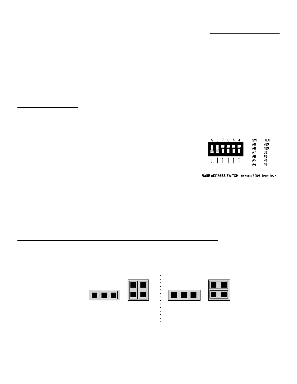
After a base address is chosen, a diagram of the switch setting is drawn on the PC screen. Set the switches on your base
address switch as shown on Figure 1-1. Unless there is already a board in your system which uses address 300 hex (768
decimal) then you can leave the switches as they are set at the factory.
In the diagram, the CIO-DAS16 is set for base address 300h. That means the
DAS-16 compatible section of the board is at 300h and the PIO-12 compatible
section of the board is at 310h (784 Decimal).
When the 4 addresses of the 8255 digital I/O (PIO-12) are in use, the
CIO-DAS16 occupies 20 consecutive addresses and is addressable on 32 address
boundaries. Address boundaries of 32 are 300h, 320h, 340h, 360h, etc.
Figure 1-1. Base Address Switches
Because the MetraByte DAS-16 occupies only 16 addresses, it is addressable at 300h, 310h, 320h, 330h etc. If you have
written software that assumes the DAS-16 base address is on a 16 address boundary and it is too much trouble to change
the address in software, the CIO-DAS16 can be made to occupy only 16 addresses and address on 16 address boundaries.
If you want to address the CIO-DAS16 on a 16 boundary address, such as 310h, 330h, 350h etc., you will not be able to
use the additional 24 digital I/O lines on the rear connector.
1.2 MODIFYING THE CIO-DAS16 FOR COMPATIBLE ADDRESSES
There are two jumpers on the CIO-DAS16, J3 and J4, which disable or enable the 8255. The jumpers must be configured
as a pair, according to either the (A) or (B) configuration in Figure 1-2.
Figure 1-2. Odd Address Jumpers
1
J3
J4
PIO-12 is not active at any address.
(B) DAS 16 POSITION
Board will address at 300H, 310H, 320H, etc.
J3
J4
CIO-DAS16 PIO-12 KNOCK OUT JUMPERS - The CIO-DAS16 is shipped in the (A)
configuration. It should be left this way unless you want to use odd addressess,
such as 310H, 330H, 350H, etc. In the (B) configuration, the 24 digital lines of
the 8255 are not usable.
PIO-12 is active at Base Address + 16
Board will address at 300H, 320H, 340H, etc.
(A)CIO-DAS16 POSITION