11 24-line digital i/o registers – Measurement Computing CIO-DAS16 User Manual
Page 29
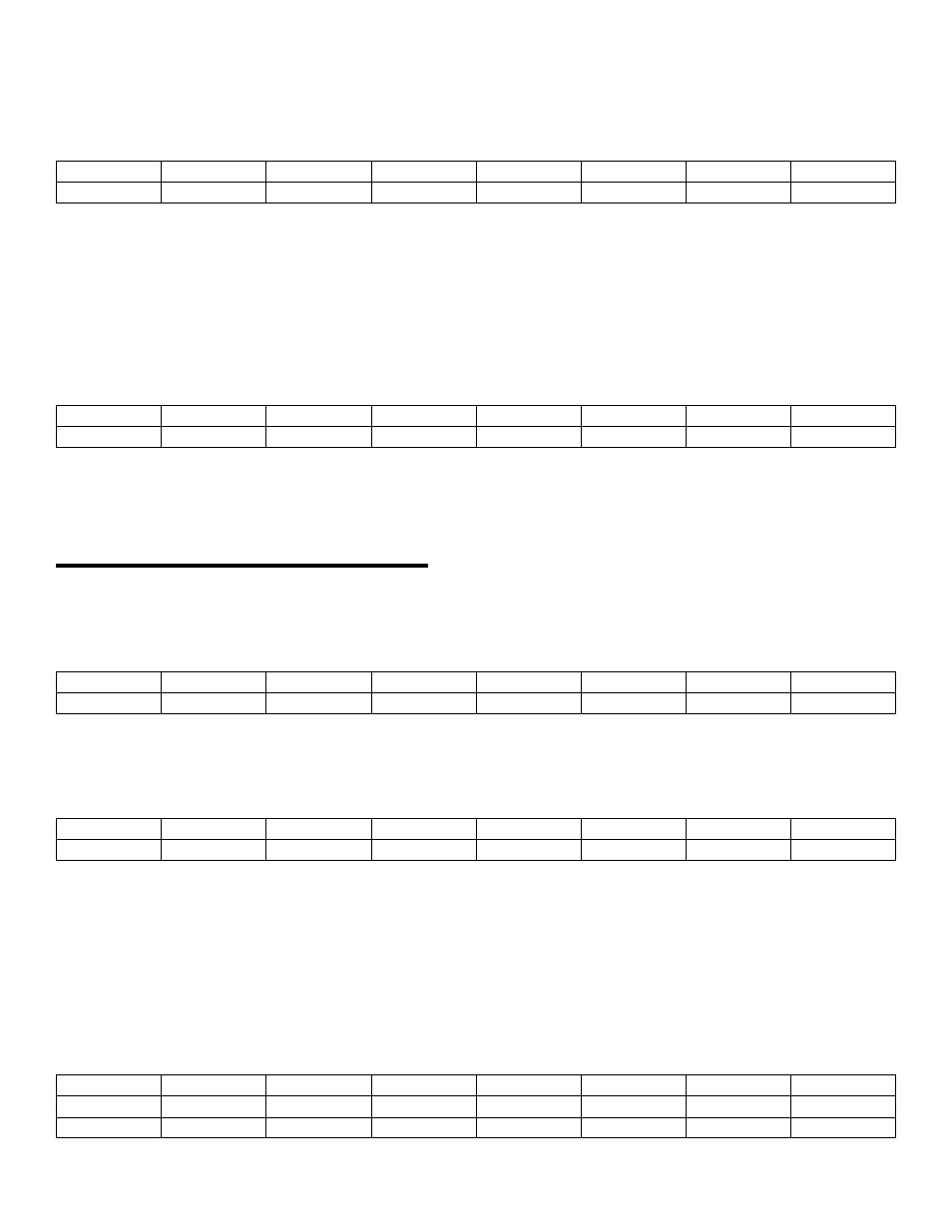
82C54 COUNTER 2 DATA
BASE ADDRESS +14
D0
D1
D2
D3
D4
D5
D6
D7
0
1
2
3
4
5
6
7
The three 82C54 counter/timer data registers may be written to and read from. Because each counter can count to
65,535, loading or reading the counter data must be a multi-step process. The operation of the 82C54 is explained in the
Intel 82C54 data sheet.
82C54 COUNTER CONTROL
BASE ADDRESS +15
D0
D1
D2
D3
D4
D5
D6
D7
0
1
2
3
4
5
6
7
This register controls the operation and loading/reading of the counters. The configuration of the 82C54 codes which
control the 82C54 chip is explained in the Intel 82C54 data sheet.
4.11 24-LINE DIGITAL I/O REGISTERS
PORT A DATA
BASE ADDRESS +16
A0
A1
A2
A3
A4
A5
A6
A7
0
1
2
3
4
5
6
7
PORT B DATA
BASE ADDRESS +17
B0
B1
B2
B3
B4
B5
B6
B7
0
1
2
3
4
5
6
7
Ports A and B may be programmed as input or output. Each is written to and read from in bytes, although for control and
monitoring purposes the individual bits are used.
Bit set/reset and bit read functions require that unwanted bits be masked out of reads and ORed into writes.
PORT C DATA
BASE ADDRESS +18
CL0
CL1
CL2
CL3
CH0
CH1
CH2
CH3
C0
C1
C2
C3
C4
C5
C6
C7
0
1
2
3
4
5
6
7
25