D / a 0, 3 analog outputs, 4 digital outputs & inputs – Measurement Computing CIO-DAS16 User Manual
Page 12
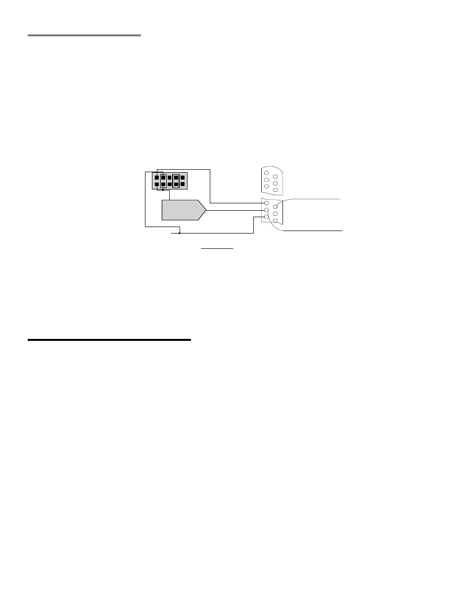
2.3 ANALOG OUTPUTS
Analog outputs are voltage outputs which can be connected to any device which will record, display or be controlled by a
voltage.
The CIO-DAS16 analog outputs are 4 quadrant multiplying DACs. This means that they accept an input voltage reference
and provide an output voltage which is inverse to the reference voltage and proportional to the digital value in the output
register.
For example, the supplied reference of -5V provides a +5V output when the value in the output register is 4095 (full scale
at 12 bits of resolution). It provides a value of 2.5V when the value in the output register is 2048 (Figure 2-6).
Figure 2-6. Analog Output Configuration
2.4 DIGITAL OUTPUTS & INPUTS
All the digital outputs and inputs on the CIO-DAS16 are TTL level. TTL is an electronics industry term, short for
Transistor Transistor Logic, that describes a standard for digital signals which are either at 0V or 5V (nominal). The
binary logic inside the PC is all TTL or LSTTL (Low power Schotky TTL).
8
3 7
9
D / A 0
2 7
D/ A 1
1 8
1 9
L L G N D
1 0
D / A 0 R E F
D/ A 1 REF
2 6
2 8
L L G N D
8
- 5 REF
X I S I X
V O L T S O U T
G R O U N D
ON BOARD - 5 REF
D / A 0
V R E F
V O U T
V OUT =
-1(V REF) * DATA
4 0 9 6
D/A REFERENCE BLOCK
CIO-DAS16 D/A CONVERTER SIGNAL CONNECTION - Jumper blocks for
internal Vref shown installed. The on-board -5V reference is internally
default configuration.
jumped. Both DACs will have a range of 0 to 5 volts. This is the factory
CIO-DAS16 37 PIN CONNECTOR