Specifications, Analog input, Chapter 5 – Measurement Computing USB-1602HS-2AO User Manual
Page 38
38
Chapter 5
Specifications
All specifications are subject to change without notice.
Typical for 25 °C unless otherwise specified.
All signal names refer to 68 pin SCSI connector, unless otherwise specified.
Analog input
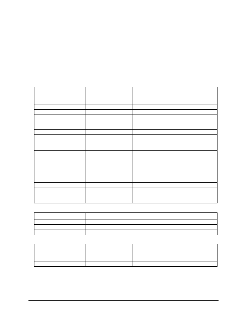
Table 1. Analog input specifications
Parameter
Conditions
Specification
A/D converter type
16-bit successive approximation type
Number of AI channels
2 SE simultaneous
Input configuration
Single-ended
Sampling method
Simultaneous; individual A/D per channel
Input ranges
±10 V, ±2.5 V, ±500 mV
Absolute maximum input
voltage
±30 V maximum (power on)
±20 V maximum (power off)
Input impedance
10 MΩ (typical, power on)
Input bias current
< 2 µA
Input bandwidth (-3 dB)
3 MHz, typical
Crosstalk
Remaining inputs grounded
100 dB (at 100 kHz )
Pacer sources
Onboard A/D clock or external digital source
(XAPCR or EXT CLK BNC)
External pacing (XAPCR or EXT CLK BNC)
See Table 12 for additional information.
Trigger sources and modes
See Table 11
Sampling rate
0.01 S/s to 2 MS/s each channel, software
programmable
Clock sources
Internal, software programmable or external pacing
Resolution
16-bits
INL (integral non-linearity)
±2.0 LSB
DNL (differential non-linearity)
±1.0 LSB
Table 2. Calibrated accuracy
Range
Accuracy
±10 V
±1 mV
±2.5 V
±0.5 mV
±500 mV
±0.15 mV
Table 3. Noise performance, note 1
Range
Typical counts
LSB rms
±10 V
8
1.3
±2.5 V
11
1.6
±500 mV
17
2.5
Note 1:
Noise distribution is determined by gathering 50,000 samples with inputs tied to ground at the
BNC connectors. Samples are gathered at the maximum specified rate.