Using the hysteresis function – Measurement Computing USB-1602HS-2AO User Manual
Page 32
USB-1602HS-2AO User's Guide
Functional Details
32
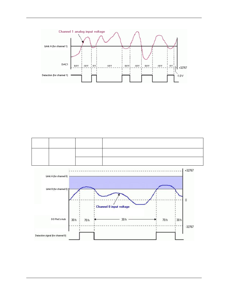
Figure 24. Channel 1 input with setpoint update on True and False
The setpoint placed on analog Channel 1 updated DAC1 with 0.0 V. The update occurred when the channel 1
input was less than setpoint limit A. When the value of the channel 1 input was above setpoint limit A, the
condition of less than limit A was false, and DAC1 was updated with –1.0 V.
Example 2:
Update mode: Update on True and False
Criteria: Channel 0 — inside window
In this example, Channel 0 is programmed with reference to two setpoints (limit A and limit B) which define a
window for that channel.
Channel Condition
State of
detect signal
Action
0
Within window
(between limit
A and limit B)
for channel 0
True
When Channel 0 analog input voltage is within the window, update the
digital output port's MSB with 70h.
False
When the above condition is false (channel 0 analog input voltage is
outside the window), update the digital output port's MSB with 30h.
Figure 25. Channel 0 input with setpoint update on True and False
You can program control outputs on each setpoint. Detection for channel 0 can be used to update the digital
output port's most significant byte with one value when the analog input voltage is within the shaded region
(70 h), and update with a different value when the analog input voltage is outside the shaded region (30 h).
Using the hysteresis function
Update mode: N/A, the hysteresis option has a forced update built into the function