Setpoint configuration, See figure 23) – Measurement Computing USB-1602HS-2AO User Manual
Page 30
USB-1602HS-2AO User's Guide
Functional Details
30
Criteria
– input signal is equal to X
Action - driven by condition
Window*
(non-hysteresis
mode)
Inside (B < X < A)
Outside: B > X; or X > A
(choose one)
True only:
If True, then output value 1
If False, then perform no action
True and False:
If True, then output value 1
If False, then output value 2
Window*
(hysteresis mode)
Above A (X > A)
Below B (X < B)
(both conditions are checked in
hysteresis mode)
Hysteresis mode (forced update):
If X > A is True, then output value 2 until X < B is True,
then output value 1.
If X < B is True, then output value 1 until X > A is True,
then output value 2.
This is saying:
(a) If the input signal is outside the window high, then output
value 2 until the signal goes outside the window low,
and
(b) if the signal is outside the window low, then output value 1
until the signal goes outside the window high.
There is no change to the detect signal while within the
window.
* Value A defines the upper limit of the Window, and Value B defines the lower limit.
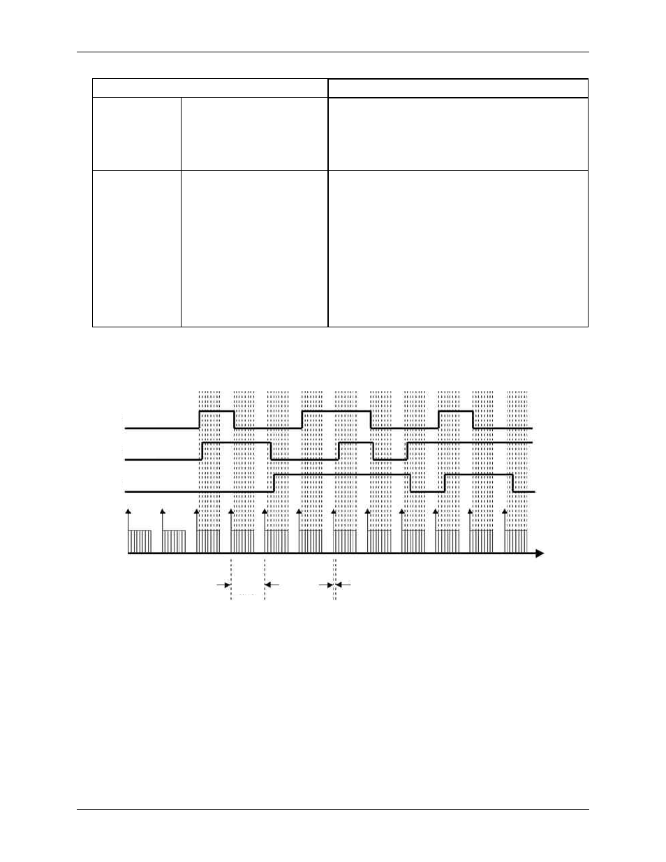
The detect signal has the timing resolution of the scan period, as shown in Figure 23. The detect signal can
change no faster than the scan frequency (1/sampling period.)
Figure 23. Detection signals for channels 1, 2, and 3
Each channel in the scan group can have one detection setpoint. There can be no more than 16 total setpoints
total applied to channels within a sampling group.
Detection setpoints act on 16-bit data only. When reading the counters as 32-bit, data is returned 16-bits at a
time. The lower word, the higher word, or both lower and higher words can be part of the scan group. Each
counter input channel can have one detection setpoint for the counter's lower 16-bit value, and one detection
setpoint for the counter's higher 16-bit value.
Setpoint configuration
You program all setpoints as part of the pre-acquisition setup, similar to setting up an external trigger. Each
setpoint acts on 16-bit data, so each has two 16-bit compare values: a high limit (limit A) and a low limit (limit
B). These limits define the setpoint window.
You can set the 16-bit high limit (limit A) and the 16-bit low limit (limit B) with software.
Detect1
Detect2
Detect3
Acquisition stream
Scan Group
Sampling
Period
1 s