Mapped channels, Counter input modes, Counter mode – Measurement Computing USB-1602HS-2AO User Manual
Page 22
USB-1602HS-2AO User's Guide
Functional Details
22
When reading synchronously, all counters are set to zero at the start of an acquisition. When reading
asynchronously, counters may be cleared on each read, count up continually, or count until the 16-bit or 32-bit
limit has been reached. See the counter mode descriptions below.
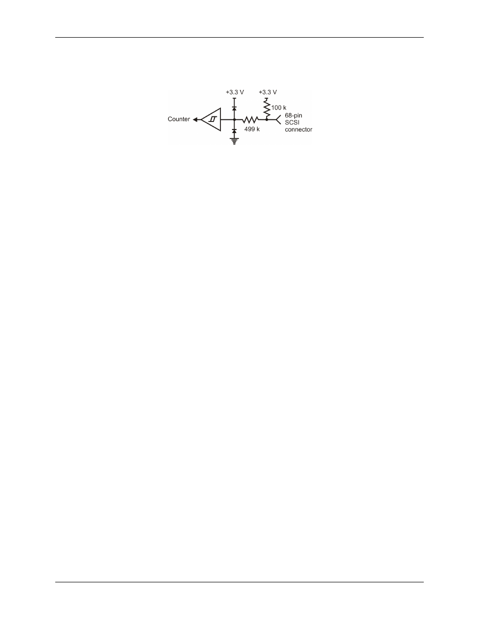
Figure 11. Typical USB-1602HS-2AO counter channel
Mapped channels
A mapped channel is one of four counter input signals (CTR0 to CTR3) that can get multiplexed into a counter
module. The mapped channel can participate with the counter's input signal by gating the counter, latching the
counter, and so on. The four possible choices for the mapped channel are the four counter input signals (post-
debounce).
A mapped channel can be used to:
gate the counter
decrement the counter
latch the current count to the count register
Usually, all counter outputs are latched at the beginning of each scan within the acquisition. However, you can
use a second channel — known as the mapped channel — to latch the counter output.
Counter input modes
The USB-1602HS-2AO supports the following modes:
Counter
Period
Pulse width measurement
Timing
Program the counter operation mode with software.
Counter mode
A counter can be asynchronously read with or without clear on read. The asynchronous read-signals strobe
when the lower 16-bits of the counter are read by software. The software can read the counter's high 16-bits
some time later after reading the lower 16-bits. The full 32-bit result reflects the timing of the first
asynchronous read strobe.
The following counter mode options are selectable with software.