Using multiple inputs to control one dac output – Measurement Computing USB-1602HS-2AO User Manual
Page 33
USB-1602HS-2AO User's Guide
Functional Details
33
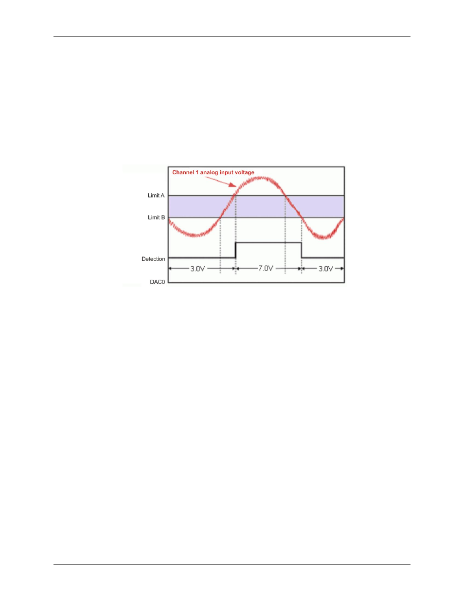
Criteria used: Window criteria for above and below the set limits
Figure 26 shows analog input Channel 1 with a setpoint which defines two 16-bit limits — Limit A (High) and
Limit B (Low). These limits are applied in the hysteresis mode and DAC channel 0 is updated accordingly.
In this example, Channel 1's analog input voltage is used to update DAC0, as follows:
When outside the window, low (below limit B) DAC0 is updated with 3.0 V. This update remains in effect
until the analog input voltage goes above Limit A.
When outside the window, high (above limit A), DAC0 is updated with 7.0 V. This update remains in
effect until the analog input signal falls below limit B. At that time we are again outside the limit "low" and
the update process repeats itself.
Hysteresis mode can also be done with the digital output port's most significant byte instead of a DAC.
Figure 26. Channel 1 in hysteresis mode
Using multiple inputs to control one DAC output
Update mode: Rising edge, for each of two channels
Criteria used: Inside window, for each of two channels
Figure 27 shows how multiple inputs can update one output. In this figure, analog output channel DAC1 is
being updated. Analog input Channel 1 has an inside-the-window setpoint applied. Whenever Channel 1's input
goes inside the programmed window, DAC1 will be updated with 3.0 V.
Analog input Channel 2 also has an inside-the-window setpoint applied. Whenever channel 2's input goes inside
the programmed window, DAC1 is updated with –7.0 V.