Digital outputs and pattern generation – Measurement Computing USB-1602HS-2AO User Manual
Page 19
USB-1602HS-2AO User's Guide
Functional Details
19
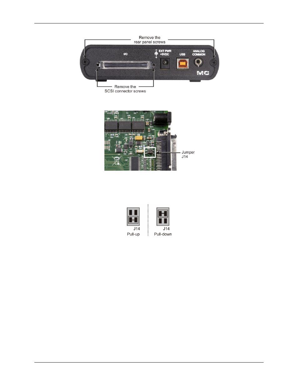
Figure 8. Location of rear panel screws
2. Slide the board out of the housing and locate jumper
J14
.
Figure 9. Location of J14
3. Configure jumper J14 for either pull-up or pull-down configuration (refer to Figure 10).
o For pull-up, place the J14 shorting block across pins 1 and 2.
o For pull-down, place the J14 shorting block across pins 3 and 4.
Figure 10. J14 configuration
4. Slide the board into the housing.
5. Replace the 4 screws on the rear panel.
Digital outputs and pattern generation
Digital outputs can be updated asynchronously at any time before, during, or after an acquisition. The USB-
1602HS-2AO can generate a digital pattern at up to 4 MS/s.
Digital pattern generation is clocked with either the internal D/A scan clock or with an external D/A input
clock. Digital patterns can be generated along with D/A waveforms. They are paced by the same selected clock.
The on-board programmable clock generates updates ranging from once every 1000 seconds to 1 MHz,
independent of the acquisition rate.
The digital outputs are driven low at power up and reset.