Measurement Computing USB-1602HS-2AO User Manual
Page 14
USB-1602HS-2AO User's Guide
Installing the USB-1602HS-2AO
14
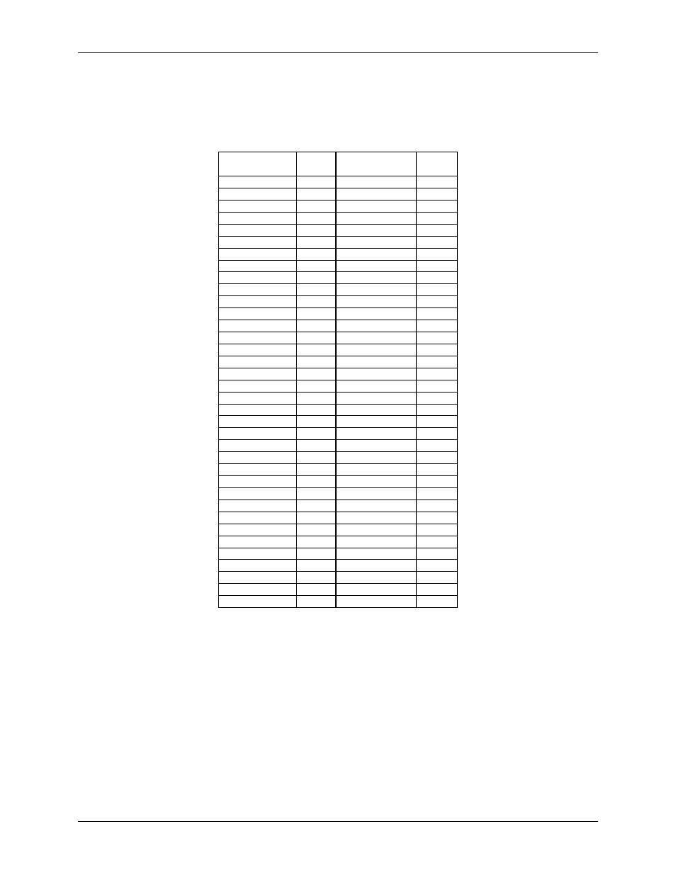
TB-102 screw terminal board connector to SCSI connector pin out
The TB-102 terminal board is shown here. The table below lists how signals on the TB-102 are mapped to the
signals on the 68-pin SCSI connector.
Pin mapping between the TB-102 terminal board and the 68-pin SCSI connector
TB1 screw
terminals
SCSI
pin
TB2 screw
terminals
SCSI
pin
AGND
1
AGND
35
Reserved
2
Reserved
36
AGND
3
AGND
37
Reserved
4
Reserved
38
AGND
5
AGND
39
VCAL
6
DAC0
40
+5VOUT
7
DAC1
41
AGND
8
AGND
42
DIN0
9
DOUT0
43
DIN1
10
DOUT1
44
DIN2
11
DOUT2
45
DIN3
12
DOUT3
46
DIN4
13
DOUT4
47
DIN5
14
DOUT5
48
DIN6
15
DOUT6
49
DIN7
16
DOUT7
50
DIN8
17
DOUT8
51
DIN9
18
DOUT9
52
DIN10
19
DOUT10
53
DIN11
20
DOUT11
54
DIN12
21
DOUT12
55
DIN13
22
DOUT13
56
DIN14
23
DOUT14
57
DIN15
24
DOUT15
58
CTR4A
25
CTR0
59
CTR4B
26
CTR1
60
CTR4Z
27
CTR2
61
CTR5A
28
CTR3
62
CTR5B
29
TMR/PWM0
63
CTR5Z
30
TMR/PWM1
64
CTR6A
31
DIGTRIG
65
CTR6B
32
XAPCR
66
CTR6Z
33
XDPCR
67
DGND
34
DGND
68
DGND
*
DGND
*
EGND
**
EGND
**
* Extra digital ground connectors
** EGND is connected to the SCSI connector shell.