Controlling analog and digital outputs, Update latency – Measurement Computing USB-1602HS-2AO User Manual
Page 35
USB-1602HS-2AO User's Guide
Functional Details
35
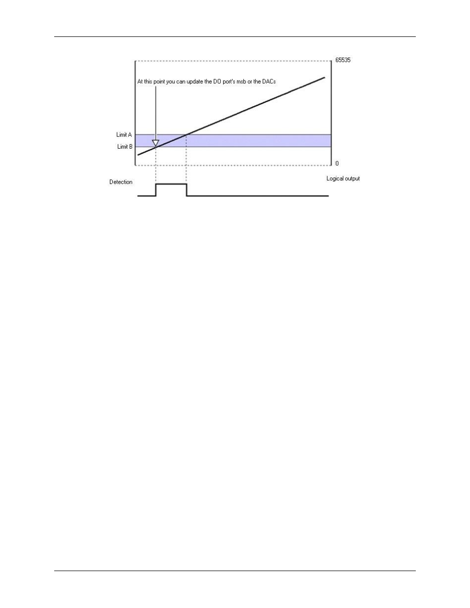
Figure 28. CTR1 in totalizing counter mode, inside the window setpoint
Controlling analog and digital outputs
You can program each setpoint with an 8-bit digital output byte and corresponding 8-bit mask byte. When the
setpoint criteria is met, the digital output port's most significant byte (MSB) can be updated with the given byte
and mask. You can also program each setpoint with a 16-bit DAC update value. Either DAC output can be
updated in real time.
In hysteresis mode, each setpoint has two forced update values. Each update value can drive one DAC or the
digital output port's most significant byte. In hysteresis mode, the outputs do not change when the input values
are inside the window. One update value gets applied when the input values are less than the window, and a
different update value gets applied when the input values are greater than the window.
Update on True and False uses two update values. The update values can drive DACs or the digital output port's
most significant byte.
The digital output port's most significant byte is updated one sample period after the detection setpoint channel
is sampled, plus up to 250 ns for data transfer from the detection setpoint channels. DAC output is updated one
sample period after the detection setpoint channel is sampled, plus up to 1 µs for data transfer from the
detection setpoint channels and data shifting out to the D/A converter. Update latencies can be improved with
an increased sample rate.
When using setpoints to control the DAC outputs, increased latencies may occur if attempting to stream data to
DACs or pattern digital output at the same time. The increased latency can be as long as the period of the DAC
pacer clock. For these reasons,
avoid streaming outputs on any DAC or pattern digital output when using
setpoints to control DACs
.
Update latency
USB-1602HS-2AO channels are read almost immediately. The response for a channel input detection does not
occur until the next reading is taken, during the next tick of the acquisition clock. The maximum update latency
is one sample period plus 250 ns for the most significant byte (MSB) of the digital output port, and 1 µs for
DAC updates.
The detection circuit works on data that is put into the acquisition stream at the sample rate. This data is
acquired according to the pre-acquisition setup (sampling group, sample period, etc.) and returned to the PC.
Counters are latched into the acquisition stream when sampling begins. The actual counters may be counting
much faster than the sample rate, and therefore only every 10
th
, 100
th
, or n
th
count shows up in the acquisition
data.
As a result, you can set a small detection window on a totalizing counter channel and have the detection setpoint
"stepped over" since the sample period was too long. Even though the counter value stepped into and out of the
detection window, the actual values going back to the PC may not. This is true no matter what mode the counter
channel is in.