Block diagram, Synchronous analog, digital, and counter sampling, Input clock pacing – Measurement Computing USB-1602HS-2AO User Manual
Page 17
USB-1602HS-2AO User's Guide
Functional Details
17
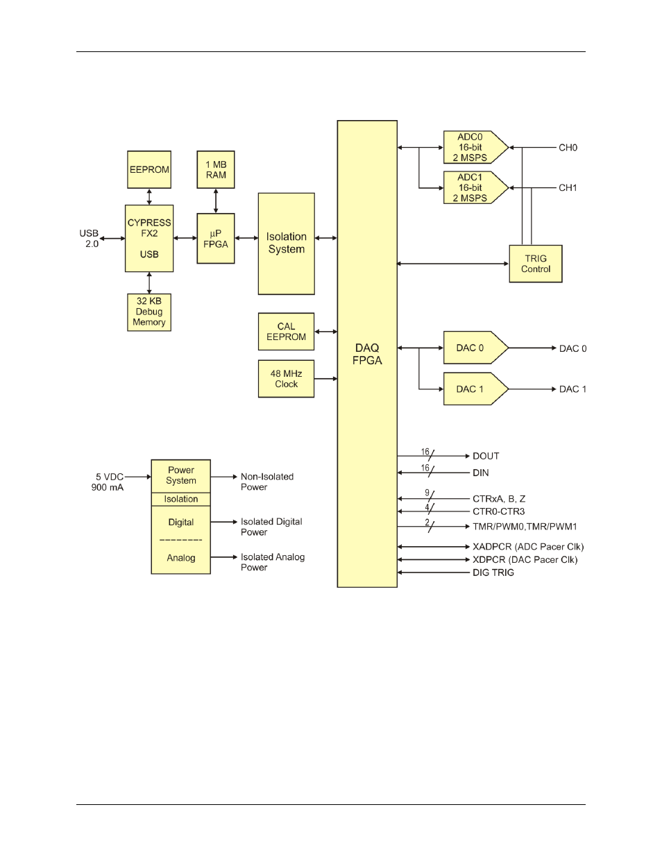
Block diagram
USB-1602HS-2AO functions are illustrated in the block diagram shown here.
Figure 7. USB-1602HS-2AO functional block diagram
Synchronous analog, digital, and counter sampling
The USB-1602HS-2AO samples all analog, digital, and counter inputs simultaneously, while also generating up
to two analog outputs and digital pattern outputs at the same time.
The maximum analog input sampling rate is 2 MS/s. Digital channels (digital input and counter channels) can
be sampled at rates up to 8 MS/s for one channel when no analog channels are sampled, and rates of up to
2 MS/s when analog channels are also sampled.
Input clock pacing
Analog, digital, and counter inputs can be sampled based on either an internal programmable input pacer or
with an external clock source (
XAPCR
pin on the SCSI connector or the
EXT CLK
BNC connector). Analog
channels can be paced from 0. 5 µs to 1000 seconds in 20.83 ns steps. Digital and counter inputs can be paced
from 250 ns to 1 second in 20.83 ns steps.