Quadrature detectors, Overview – Measurement Computing USB-1602HS-2AO User Manual
Page 26
USB-1602HS-2AO User's Guide
Functional Details
26
Trigger after stable mode behaves more like a traditional debounce function: rejecting glitches and only passing
state transitions after a required period of stability. Trigger after stable mode is used with electro-mechanical
devices like encoders and mechanical switches to reject switch bounce and disturbances due to a vibrating
encoder that is not otherwise moving. The debounce time should be set short enough to accept the desired input
pulse but longer than the period of the undesired disturbance as shown in Figure 17.
Figure 17. Optimal debounce time for trigger after stable mode
Quadrature detectors
Overview
Quadrature detectors are used to calculate the relative or absolute position of a quadrature encoder, and to
determine its rotational speed. Each quadrature detector supports phase A, B, and Z input signals (0 , 90 , and
zero). When reading phase A, phase B, and index Z signals, the positioning, direction, and velocity data can be
calculated.
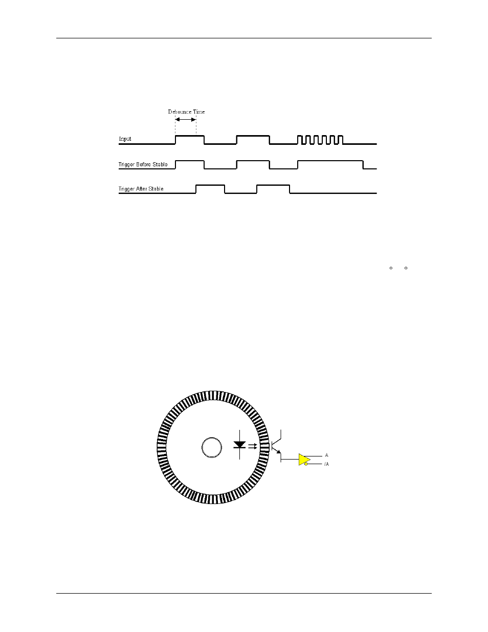
Quadrature encoders generally have three outputs: A, B, and Z. The A and B signals are pulse trains driven by
an optical sensor inside the encoder. As the encoder shaft rotates, a laminated optical shield rotates inside the
encoder. The shield has three concentric circular patterns of alternating opaque and transparent windows
through which an LED shines. There is one LED and one phototransistor for each of the concentric circular
patterns. One phototransistor produces the A signal, another phototransistor produces the B signal and the last
phototransistor produces the Z signal. The concentric pattern for A has 512 window pairs (or 1024, 4096, etc.)
When using a counter for a trigger source, use a trigger value of at least 1. Since all counters start at zero with
the initial scan, there is no valid reference in regard to rising or falling edge. Setting a pre-trigger to 1 or more
ensures that a valid reference value is present, and that the first trigger is legitimate.
Figure 18. Concentric pattern for output A
The concentric pattern for B has the same number of window pairs as A, except that the entire pattern is rotated
by ¼ of a window-pair. Thus the B signal is always 90º out of phase from the A signal. The A and B signals
pulse 512 times (or 1024, 4096, etc.) per complete rotation of the encoder.
The concentric pattern for the Z signal has only one transparent window and therefore pulses only once per
complete rotation. Representative signals are shown in Figure 19.