Trigger after stable mode, Trigger before stable mode – Measurement Computing USB-1602HS-2AO User Manual
Page 24
USB-1602HS-2AO User's Guide
Functional Details
24
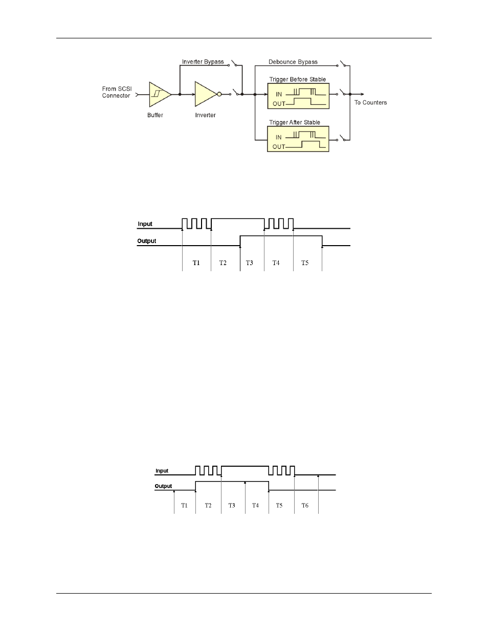
Figure 12. Debounce model block diagram
Trigger after stable mode
In the trigger after stable mode, the output of the debounce module does not change state until a period of
stability has been achieved. This means that the input has an edge, and then must be stable for a period of time
equal to the debounce time.
Figure 13. Debounce module
– trigger after stable mode
T1 through T5 indicate time periods. In trigger after stable mode, the input signal to the debounce module is
required to have a period of stability after an incoming edge, in order for that edge to be accepted (passed
through to the counter module.) For this example, the debounce time is equal to T2 and T5.
T1 – In Figure 13, the input signal goes high at the beginning of time period T1, but never stays high for a
period of time equal to the debounce time setting (equal to T2 for this example.)
T2 – At the end of time period T2, the input signal has transitioned high and stayed there for the required
amount of time—therefore the output transitions high. If the input signal does not stabilize in the high state
long enough, no transition would have appeared on the output and the entire disturbance on the input would
have been rejected.
T3 – During time period T3, the input signal remained steady. No change in output is seen.
T4 – During time period T4, the input signal has more disturbances and does not stabilize in any state long
enough. No change in the output is seen.
T5 – At the end of time period T5, the input signal has transitioned low and stayed there for the required
amount of time—therefore the output goes low.
Trigger before stable mode
In the trigger before stable mode, the output of the debounce module immediately changes state, but will not
change state again until a period of stability has passed. For this reason the mode can be used to detect glitches.
Figure 14. Debounce module
– Trigger before stable mode
T1 through T5 indicate time periods.
T1 – In Figure 14, the input signal is low for the debounce time (equal to T1); therefore when the input
edge arrives at the end of time period T1, it is accepted and the output (of the debounce module) goes high.
Note that a period of stability must precede the edge in order for the edge to be accepted.