Functional details, Front panel, Bnc connectors – Measurement Computing USB-1602HS-2AO User Manual
Page 15: Status leds, Rear panel, Scsi connector
15
Chapter 3
Functional Details
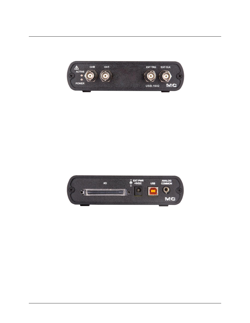
Front panel
Figure 4. USB-1602HS-2AO front panel
BNC connectors
The USB-1602HS-2AO has four BNC connectors that provide connections for the following signals:
Two single-ended analog inputs
External digital trigger input
External pacer clock input
These signals are also available on the 68-pin SCSI connector.
Status LEDs
The
POWER
LED lights up after the device is enumerated by the system. The
ACTIVE
LED lights up when the
USB-1602HS-2AO is transmitting or receiving data.
Rear panel
Figure 5. USB-1602HS-2AO rear panel
SCSI connector
The 68-pin SCSI connector provides connections for all I/O signals except for analog input: Refer to page 12
for the connector pin out.
Two analog outputs (DAC0 and DAC1)
16 digital inputs (DIN1 to DIN15)
16 digital outputs (DOUT1 to DOUT15)
Four counters (CTR0 to CTR3). Two counters may be gated.
Three quadrature detectors (CTR4 A, B, and Z to CTR6 A, B, and Z)
Two timer/pulse outputs (TMR/PWM0 to TMR/PWM1)
Digital trigger input (DIG TRIG)
Input pacer clock (XAPCR)
Output pacer clock (XDPCR)
Analog ground (AGND)
Digital ground (DGND)
Calibration (VCAL)
+5V PWR