Hapter, Nstalling a, Itescape – Leprecon Litescape dimmer User Manual
Page 56: Rchitectural, Ouselite, Ystem
Litescape User’s Manual, Page 40
C
HAPTER
14: I
NSTALLING A
L
ITESCAPE
™ A
RCHITECTURAL
H
OUSELITE
S
YSTEM
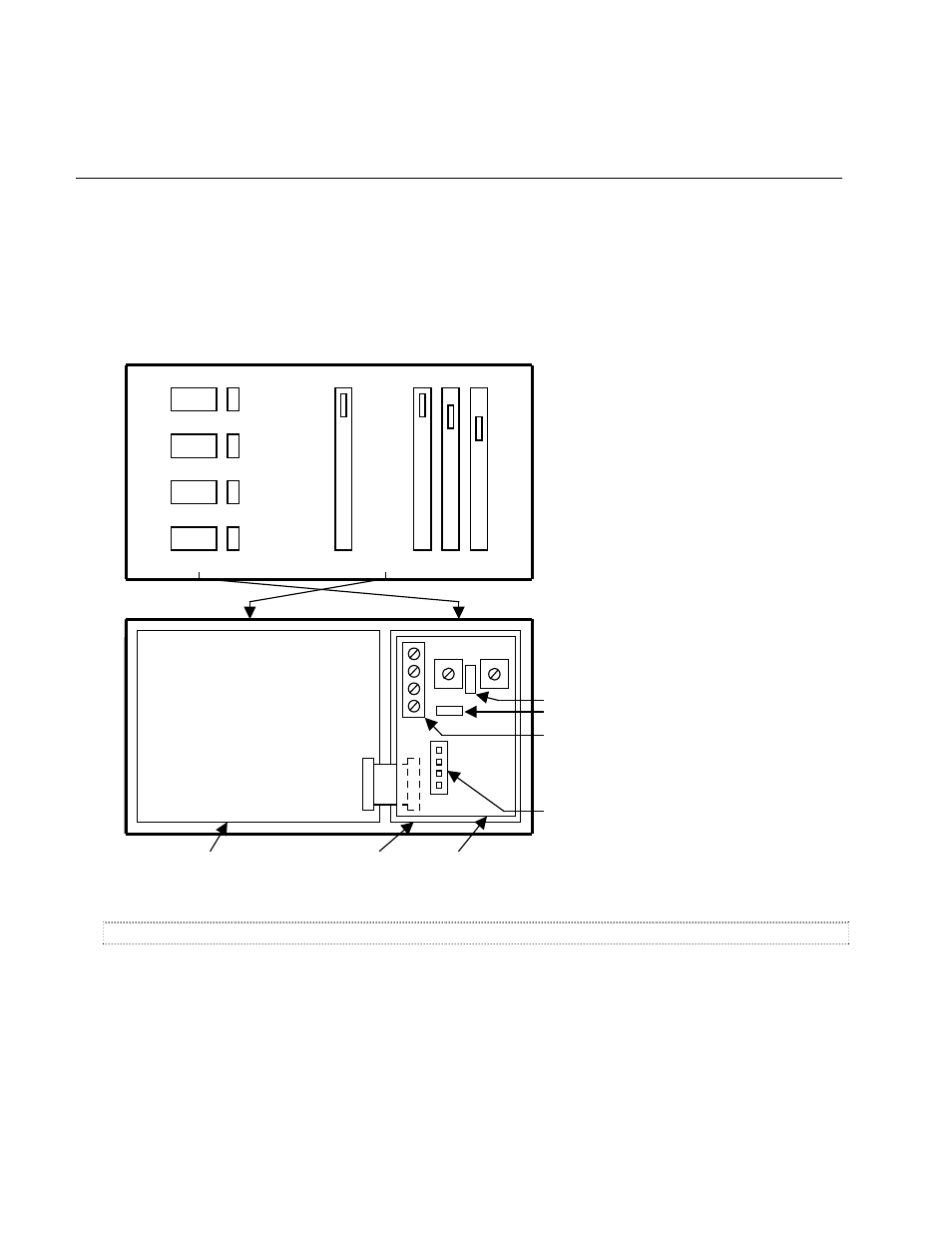
A Typical Houselite Wall Panel
The figure below shows a typical HL Wall Panel, in this case a 3-Button/3-Fader panel. The rear view
shows the location of important connectors, switches and jumpers that are discussed next.
3-FADER
MAST
ER
1
2
3
3-BUTTON
OFF
3
2
1
FADER BOARD
Front View
Rear View
PRESET BOARD
PROCESSOR BOARD
ROOM PANEL
1
1
1
PRIORITY JUMPER: UP = HIGH PRIORTY PANEL
TERMINATION JUMPER: LEFT = TERMINATED
SYSTEM CONNECTOR:
1 = V+ (Top)
2 = SIG -
3 = SIG +
4 = V- (Bottom)
AUX INPUT CONNECTOR:
4 = CLOSURE 3 (Top)
3 = CLOSURE 2
2 = PRIORITY (keyswitch)
1 = GROUND (Bottom)
Setting the Internal Switches
It is easier to set the switches and jumpers before installing the Wall Panel into the electrical box.
Set the
ROOM switch to the desired room number. Only values 1-8 are valid.
Set the
PANEL switch to a unique value between 1 and 12. For any one ROOM, no two Wall Panels can
have the same PANEL number. Otherwise, unpredictable results can occur. To disable a wall panel, set
its PANEL switch to 13, 14 or 15.
Set the
PRIORITY jumper to either HIGH (up) or LOW priority. If the jumper is missing, then the panel will
default to HIGH priority.