Gasboy Fuel Point Ground Antenna User Manual
Page 9
Introduction
Ground Antenna System Layout
Page 5
MDE-4530 Fuel Point Ground Antenna Installation Instructions · November 2005
This is the natural alignment for fueling; so drivers will not require special training.
• Other locations (other than aligned with nozzle) are acceptable but should be
supplemented with a sign or other visual aid like a line painted on pavement.
• The ground antenna is a 6 inches diameter molded ring. Read radius for vehicles is 20
inches to 48 inches, dependent on the type of vehicle being fueled. The closer the vehicle
ring or antenna is above the ground antenna, the greater the read zone.
G-Ring Height
Above Pavement
Effective Communications
(Read Radius)
Typical Vehicle Types for this range
12”
48”
Cars, Small Vans and Trucks
18”
30”
Transit Buses, OTR Trucks
24”
24”
School Buses
30”
20”
Large Vehicles
• It is important for vehicle G-Rings to be centered over the ground antenna. When lanes are
not clearly defined, provision should be made to ensure that vehicles stop to fuel with the
vehicle over the center of the ground antenna (spaced at a proper distance from the pump).
A painted center line or traffic control devices (traffic cones) can be used to funnel
vehicles to the pump at the proper spacing.
• In applications with more than one dispenser per lane, the ground antennas must be
located so that the effective read diameters do not overlap. Spacing the ground antenna
(spacing pumps) at a distance of 10’ center-to-center will ensure proper operation. Refer
the chart about this spacing aspect on
• Normally, vehicles should approach the pump to fuel from the same direction. For
applications where the fill tube varies from side to side, it is important to locate the ground
antenna in the center of the fueling lane and to locate the vehicle G-Rings at or very close
to the center of the vehicle (side to side).
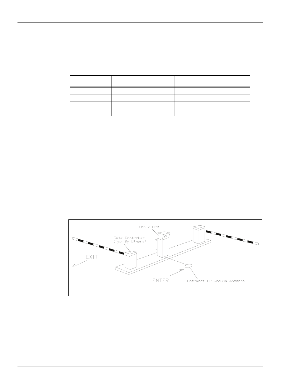
Figure 1-2 Gate Installation (Typical)