Gasboy gate system control wiring – Gasboy 1000 Series Fuel Management System Installation User Manual
Page 53
MDE-4344A Series 1000 Fuel Management System Installation Manual · November 2008
Page 49
Gasboy Gate System Control Wiring
System and Pump/Dispenser Wiring
Gasboy Gate System Control Wiring
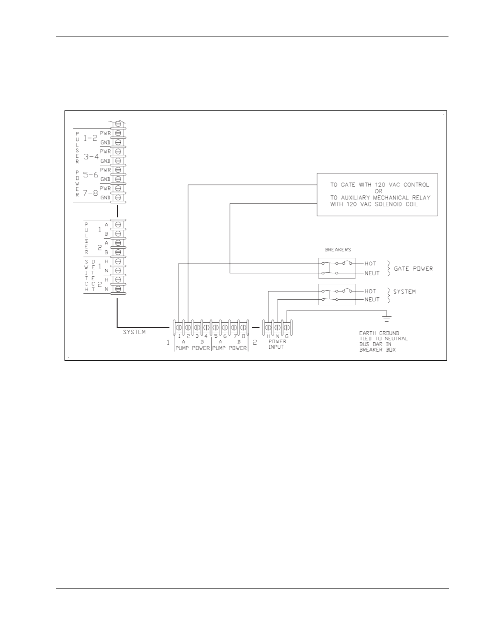
Figure 4-23: Gasboy Gate System Control Wiring
Notes:1) The Series 1000 Gate System will only directly switch 115 VAC (3/4 HP max.). If
your gate uses a different control voltage (12 V, 24 V, and so on) or exceeds 3/4 HP
max. rating, an auxiliary mechanical relay with a 115 VAC solenoid coil must be
used to switch the control voltage to the gate.
2) There are no connections made to the Pulser/Reset complete terminal block.
3) The Series 1000 allows a loadable timeout value (1-255 seconds) during which it
keeps the gate relay energized. The selected time depends on the gate manufacturer’s
specification.
4) After the initial relay closure, the remainder of the gate opening and closing is
dependent upon the gate electrical system.
5) As shown, the first pump power position is used for gate control.