9852qtw2, 9853qtw2, 9853qtw1m pumps – Gasboy 1000 Series Fuel Management System Installation User Manual
Page 45
MDE-4344A Series 1000 Fuel Management System Installation Manual · November 2008
Page 41
9852QTW2, 9853QTW2, 9853QTW1M Pumps
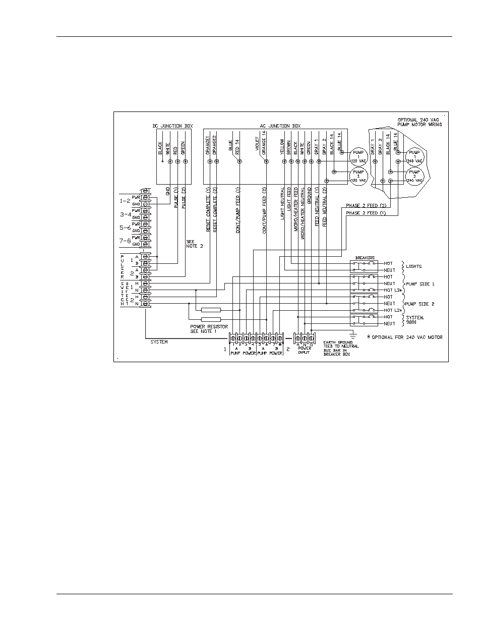
System and Pump/Dispenser Wiring
9852QTW2, 9853QTW2, 9853QTW1M Pumps
Figure 4-16: 9852QTW2, 9853QTW2, 9853QTW1M Pumps
Notes:1) The power resistor assembly is 8.2K OHM, 10 W (Part Number C05818) for 115/230
VAC domestic units and 30K OHM, 10 W (Part Number C06683) for 230 VAC
international units.
2) Before applying power, the Series 1000 Pump Control PCB jumpers must be set for
Series 9800/9820 as described in C08921 Series 1000 Start-up Manual. Failure to
properly set the jumpers will damage the Series 1000 system.
3) The wire colors may vary. Refer to current pump wiring diagrams.
4) When used with an aboveground tank, the anti-siphon valve mounted on the tank must
be driven from the EXTERNAL VALVE line, have the same operating voltage as the
pump motor, and the current draw must not exceed 1 Amp. If these conditions are not
met, it must be controlled by an external relay driven from the EXTERNAL VALVE
line. Do not connect the anti-siphon valve or external relay to the RESET
COMPLETE line. Do not connect two or more EXTERNAL VALVE lines together. If
more than one pump is drawing from the tank, separate anti-siphon valves must be
installed, or each EXTERNAL VALVE line must operate an external relay which then
operates the valve.