Gasboy 900 Series User Manual
Page 7
MDE-5061 TopKAT™ Series 900 Replacement Report Printer Kit (M11810K001) Installation Instructions · March 2013
Page 7
Installing TopKAT Series 900 Replacement Report Printer Kit
11
Replace the existing Printer DC Power Cable (C06812) with the +24 V Power Supply Cable
(M11808A001) provided in the kit and perform the following steps:
a
Plug in one end of +24 V Power Supply Cable to the 4-position DC OUT/TB2 on +24 V
Power Supply.
b
Plug in the other end of +24 V Power Supply Cable to P3 on the Printer Interface Printed
Circuit Assembly [PCA (M11777A001)].
c
Ensure to route the DC Connector through the bushing from left to right and then onto the
DC Output Connector (see
on
). Failure to route the DC Connector through
the bushing will not allow reinstalling the power supply cover without pinching the cable.
12
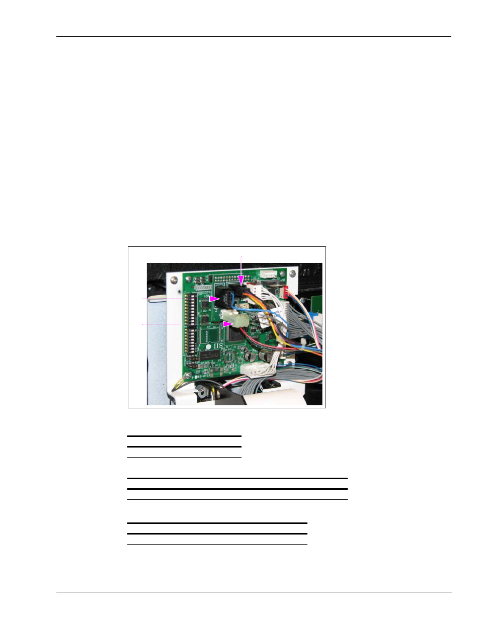
Connect the two connectors from the existing Printer Cable Assembly, the 10-position
Connector to P1 and the 6-position Connector to P2 as shown in
.
Figure 4: Attaching Power Cable to Printer Interface PCA
P2
P1
P3
13
Verify the following settings on the new Printer Controller PCA (M11960A001):
JP1
JP2
JP3
JP4
Open Open Jumper 1-2 Jumper 1-2
Switches DIP 1
Pos 1 Pos 2 Pos 3 Pos 4 Pos 5 Pos 6 Pos 7 Pos 8 Pos 9
Pos 10
Off
Off
Off
On
Off
On
Off
On
On
Off
Switches DIP 2
Pos 1
Pos 2
Pos 3
Pos 4
Pos 5 Pos 6 Pos 7 Pos 8
On
Off
Off
Off
Off
Off
Off
On