Gasboy 9800A User Manual
Page 8
Installation of the 9800A/2600A Pump Interface Kit
Page 8
MDE-4863 Gasboy® 9800A or 2600A Pump Interface Kits Installation Instructions · October 2009
9
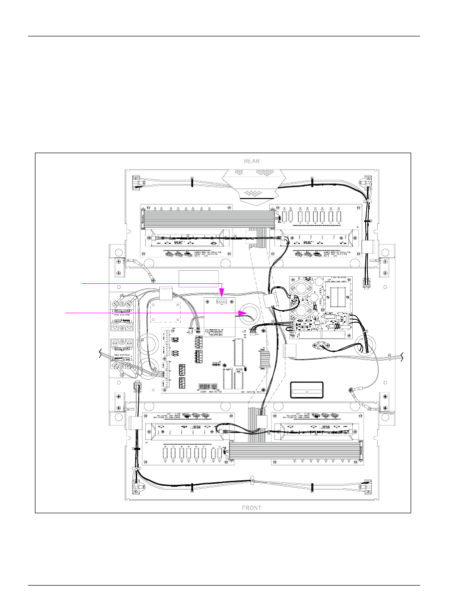
Feed the DC Cable up through the platform bushing. The DC Cable is a 4-conductor Gray
Cable with red, green, white, and black wires terminated to a 5-position connector; it is part of
the DC Conduit Assembly. Attach the DC Cable to P1 of the Pump I/F PCB (P1 is a 4-pin
connector). Ensure that you align Pin 1 of the Cable Connector with Pin 1 of the P1 Connector.
If present, Pin 5 of the Cable Connector is not used and will hang off to the end of the P1
Connector.
Figure 6: Platform Assembly
Platform
Bushing
P1
10
Connect the wiring between the Card System and DC Junction Box as shown in MDE-4341
Series 9800A/9800Q Pump and Dispenser Installation/Operation Manual.
11
Secure the Display Panel in the upright position.