Jumpers jp4 and jp5 – Gasboy 9820 User Manual
Page 9
MDE-4864 Gasboy® 9820 Pump Interface Kit Installation Instructions · October 2009
Page 9
Pulse-out I/F Board (M06587A001) Jumper Settings
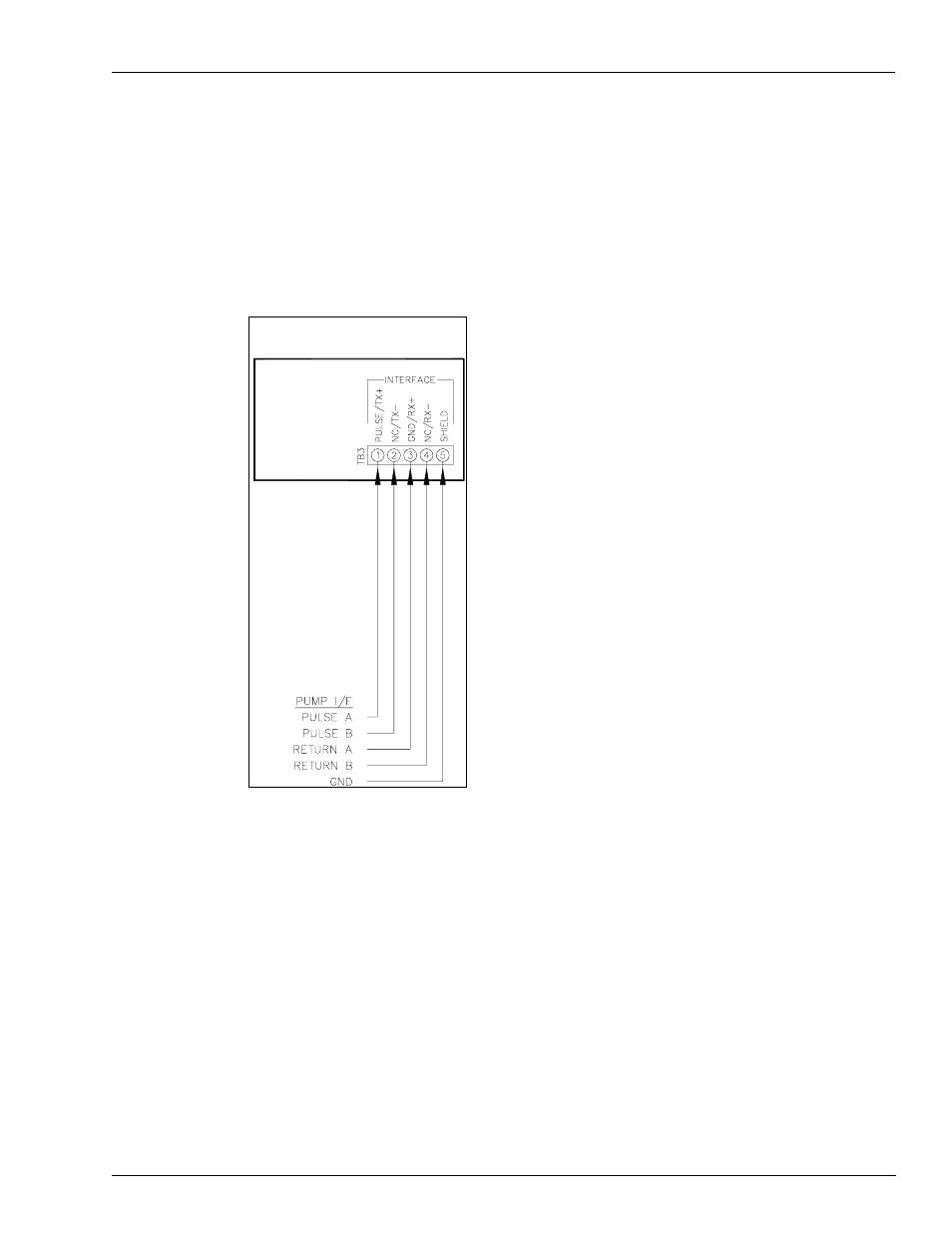
Jumpers JP4 and JP5
When this board is used in a model 9820 Pump/Dispenser, jumpers JP4 and JP5 are set to the
Q/A position.
illustrates the proper output for using a Pump I/F Board (M06587A001), jumpered to
provide two isolated pulse outputs from a single pulser (C07355 kits).
Figure 5: Dual-channel, Single-hose Pulse-out I/F
REMOTE REGISTER
Note: 1) All wiring and conduit runs must conform with all building/fire codes, all Federal,
State, and Local codes, National Electrical Code, (NFPA 70), NFPA 30, and
Automotive and Marine Service Station Code (NFPA 30A) codes and regulations.
Canadian users must also comply with the Canadian Electrical Code.
2) Refer to MDE-4567 9120K & 9820K Series AST Pumps Installation and Operation
Manual or MDE-4652 Atlas 9800 Electronics Field Installation Instructions for
complete installation instructions.
- 216S (18 pages)
- Atlas Fuel Systems Site Prep Manual (42 pages)
- Atlas Technician Programming Quick Ref (2 pages)
- ATC M05819K00X Kits (28 pages)
- Atlas Fuel Systems Owner Manual (80 pages)
- Gilbarco Global Pumping Unit Operation Manual (42 pages)
- 26 (7 pages)
- Atlas Valve Replacement Kits (10 pages)
- Atlas Fuel Systems Installation Manual (100 pages)
- 9120K (8 pages)
- 9820K (6 pages)
- Atlas Single Std. Inlet Centering Kit (8 pages)
- 8800 Atlas (1 page)
- 9120K Series Service Manual (40 pages)
- 9800A Atlas (6 pages)
- 9800 Atlas (14 pages)
- 9800 Atlas (20 pages)
- M08400 (6 pages)
- 9100 Series (8 pages)
- 9820K Series Installation (62 pages)
- 9853K (8 pages)
- 9216KTW (36 pages)
- Recommended Spare Atlas (14 pages)
- DEF Atlas (28 pages)
- 9820K Series (12 pages)
- 9800Q (1 page)
- Q Series (3 pages)
- 8753E (2 pages)
- 9152AXTW2 (1 page)
- 8800E (2 pages)
- 8800E (1 page)
- 9820Q Series (1 page)
- Atlas Start-up (230 pages)
- 2600A (12 pages)
- 2600A (2 pages)
- 9800Q Front Load Vapor (2 pages)
- 215A (1 page)
- 9800A (4 pages)
- 9820A (1 page)
- 2600A (3 pages)
- 216A (31 pages)
- 215A (2 pages)
- 9800Q Vapor (2 pages)
- Lamp Kit (2 pages)
- 9120Q Pulser (1 page)