Gasboy 9820 User Manual
Page 7
MDE-4864 Gasboy® 9820 Pump Interface Kit Installation Instructions · October 2009
Page 7
Installation of the Gasboy 9820 Pump Interface Kit
8
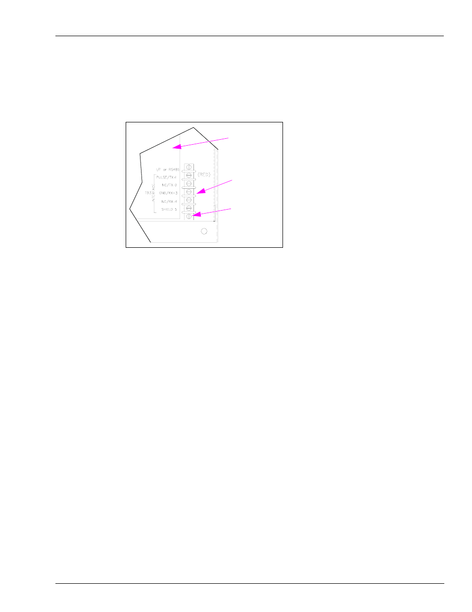
Feed the connector end of the cable into the round terminal bracket mounting hole at the
bottom-right of the chassis. Position the terminal block with the red wire in position 1. Secure
the terminal block using the #8-32 hardware.
Figure 4: Installing the Terminal Block
Chassis
Cable
#8-32 Hardware
9
Carefully route the cable and install the connector on P1 of the I/F PC Board.
10
Return the chassis to the cabinet.
11
Reconnect all the wiring.
12
Connect the new field wiring to the new terminal block according to the MDE-4567 9120K &
9820K Series AST Pumps Installation and Operation Manual.
13
Turn on the MICRO and FEED circuit breakers.
- 216S (18 pages)
- Atlas Fuel Systems Site Prep Manual (42 pages)
- Atlas Technician Programming Quick Ref (2 pages)
- ATC M05819K00X Kits (28 pages)
- Atlas Fuel Systems Owner Manual (80 pages)
- Gilbarco Global Pumping Unit Operation Manual (42 pages)
- 26 (7 pages)
- Atlas Valve Replacement Kits (10 pages)
- Atlas Fuel Systems Installation Manual (100 pages)
- 9820K (6 pages)
- 9120K (8 pages)
- Atlas Single Std. Inlet Centering Kit (8 pages)
- 8800 Atlas (1 page)
- 9120K Series Service Manual (40 pages)
- 9800A Atlas (6 pages)
- 9800 Atlas (14 pages)
- 9800 Atlas (20 pages)
- M08400 (6 pages)
- 9100 Series (8 pages)
- 9820K Series Installation (62 pages)
- 9853K (8 pages)
- 9216KTW (36 pages)
- Recommended Spare Atlas (14 pages)
- DEF Atlas (28 pages)
- 9820K Series (12 pages)
- 9800Q (1 page)
- Q Series (3 pages)
- 8753E (2 pages)
- 9152AXTW2 (1 page)
- 8800E (1 page)
- 8800E (2 pages)
- 9820Q Series (1 page)
- Atlas Start-up (230 pages)
- 9800A (4 pages)
- 9820A (1 page)
- 2600A (3 pages)
- 2600A (12 pages)
- 2600A (2 pages)
- 9800Q Front Load Vapor (2 pages)
- 215A (1 page)
- 215A (2 pages)
- 9800Q Vapor (2 pages)
- 216A (31 pages)
- Lamp Kit (2 pages)
- 9120Q Pulser (1 page)