3 - pumping unit operation and maintenance, 3 – pumping unit operation and maintenance – Gasboy Gilbarco Global Pumping Unit Operation Manual User Manual
Page 9
MDE-4447A Global Pumping Unit Operation and Service Manual · May 2008
Page 5
Flow of Liquid Through Pumping Unit and Air Eliminator
Pumping Unit Operation and Maintenance
3 – Pumping Unit Operation and Maintenance
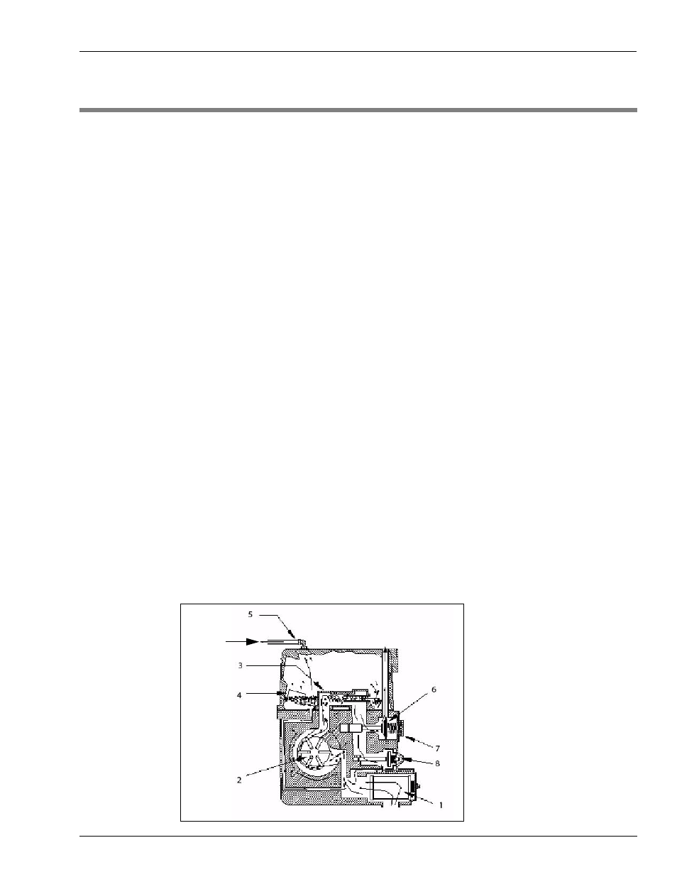
Flow of Liquid Through Pumping Unit and Air Eliminator
The Model M04920 Pumping Unit moves the product from the storage tank to the vehicle or
container in the following manner:
Note: The numbers within parentheses in the procedural steps below refer to the numbers in
.
1
The fuel is drawn from the storage tank through the strainer screen or filter (1).
2
The rotary vane pumping unit (2) pressurizes the fluid.
3
Fuel enters the centrifugal air separator assembly (3). Any air that is present is forced out of
the air tube along with a small amount of liquid into the atmospheric chamber.
4
When the liquid level in the chamber lifts the float and valve assembly (4), the liquid collected
in the atmospheric chamber is returned to the pump intake. Air is then vented to the
atmosphere through the end tube (5).
5
Air-free fuel leaving the air separator opens the control valve (6) and is pumped into the meter.
The control valve includes a built-in relief valve (7) which relieves excess pressure caused by
hot weather expansion.
6
Fuel passes through the meter where it is accurately measured, then through the hose and
nozzle to the vehicle or container being fueled.
7
Whenever the nozzle is not fully opened, some liquid is relieved into the pump through the
bypass valve (8).
Figure 3-1: Flow Diagram
Vent Tube
Discharge
Atmospheric
Chamber
Pressure
Relief
Valve
Inlet